There is no universal voltage, topology or switchgear arrangement for wind farm electrical distribution. Start with four project-specific inputs: the data at each wind turbine terminal, the collector-feeder grouping and route, the transformer and point-of-interconnection requirements, and the operating responsibilities across each contract boundary. Only that combined input set can determine an appropriate collector system and medium-voltage (MV) equipment scheme.
This guide explains how those inputs connect. It is conceptual coordination guidance, not project engineering, protection-setting, switching or approval authority. Final design must be checked by the responsible engineers against the site conditions, applicable standards, grid requirements, equipment documentation and approved operating procedures.
What electrical distribution for a wind farm includes
In a large wind plant, turbines are interconnected through a collector system rather than connected individually to the transmission network. The collector layout, conductor type and size, and whether feeders use overhead lines or buried cable all affect electrical behaviour and must be studied together (NREL, 2006).
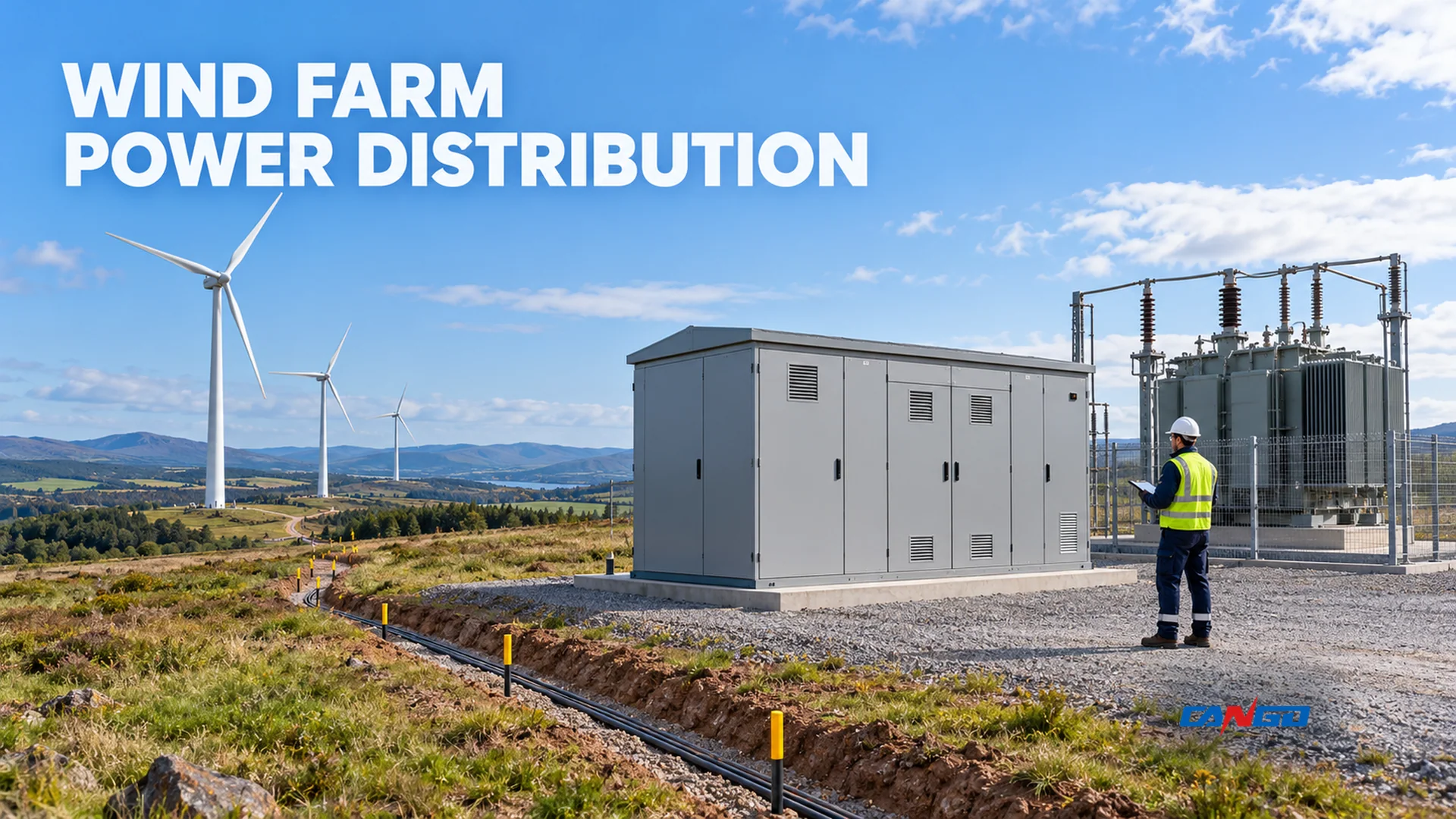
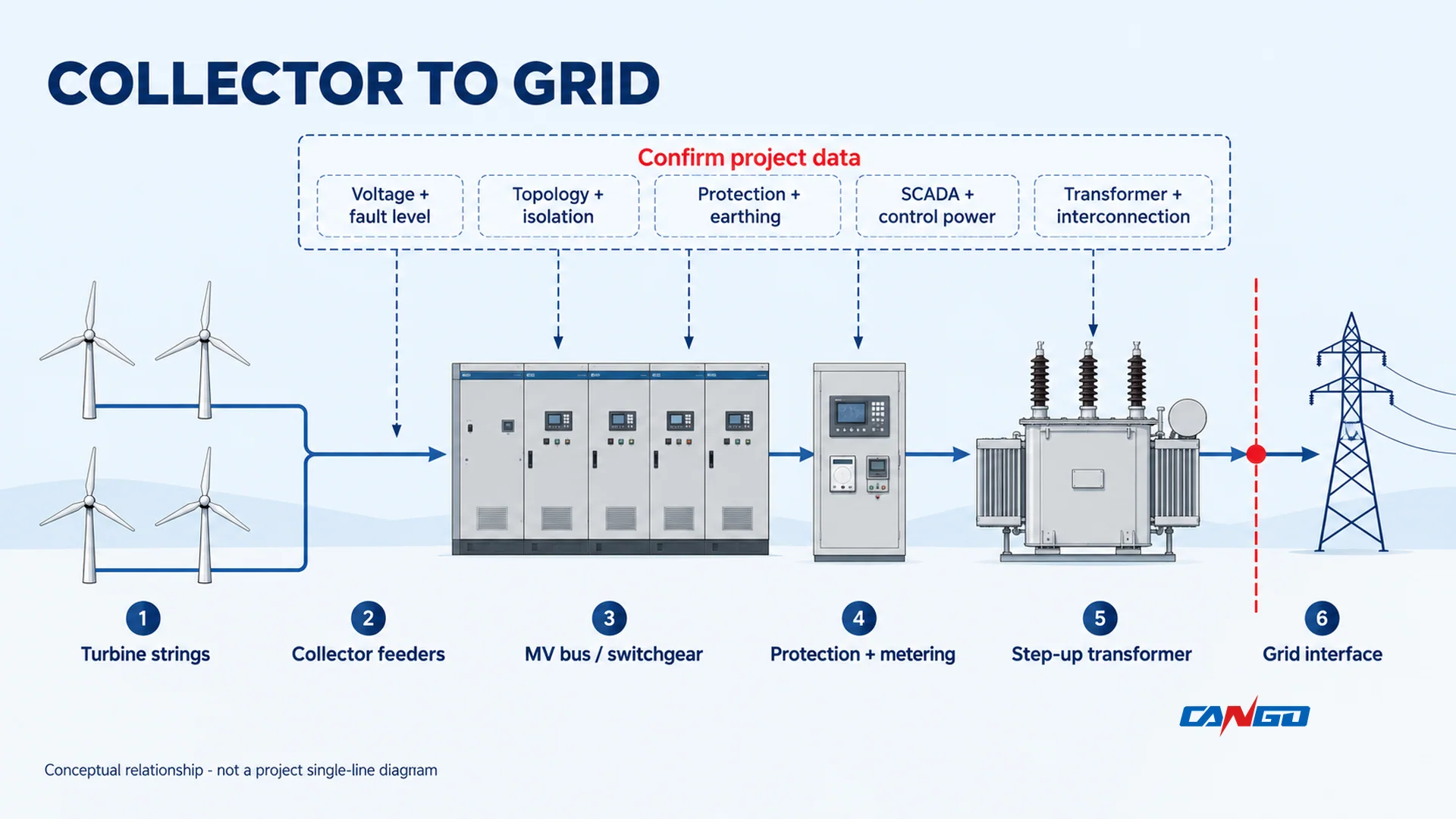
The functional chain is straightforward. Each turbine produces power at its own terminal conditions. One or more turbines connect to a collector feeder. Collectors converge on an MV bus or switching point, where the project can isolate, protect and meter circuits. A step-up transformer then establishes the voltage needed at the grid side of the project. The point of interconnection can sit beyond other equipment and assets that the wind-farm developer does not own.
That chain crosses three different boundaries:
| Boundary | What crosses it | Why it must be defined |
|---|---|---|
| Turbine terminal to collector feeder | Voltage, frequency, real and reactive power, fault contribution, protection and control signals | The collector and protection study needs the actual turbine characteristics, not a generic turbine count |
| Collector to project substation | Feeder voltage and arrangement, current, fault level, cable or line interfaces, earthing and communications | Switchgear ratings, protection coordination and transformer application depend on the aggregate system |
| Project substation to grid | Point-of-interconnection voltage, fault level, protection, metering, operating constraints and ownership | Utility requirements can change the transformer, switching and protection scope |
The diagram below makes the sequence visible. The dashed data prompts are deliberate: each can change the equipment or study output even when the physical route appears similar.
Start with the collector feeder, not a catalogue voltage
A collector feeder is more than a line on the site plan. It establishes which turbines share a conductor path, how faults and voltage changes propagate, where circuits can be isolated, and how much equipment may be affected by an outage or maintenance activity.
Collector design also depends on installation conditions. A 2010 NREL/ORNL paper identifies conductor selection, soil thermal properties, installation, splicing, concentric grounding and code requirements as part of cable application; overhead lines introduce a different set of structures, conductors and environmental constraints (NREL/ORNL, 2010).
Do not turn those considerations into an article-level default cable size, burial depth or clearance. They require route, soil, thermal, fault, voltage-drop and mechanical studies. A supplier quoting from a single voltage and a turbine count is missing the information that makes the offer comparable.
Build a single-line diagram that exposes the interfaces
A useful wind-farm single-line diagram should show the electrical path and the points where responsibility changes:
- Each turbine terminal or turbine transformer, as applicable, with its connection to a named collector feeder.
- The collector-feeder topology, including every point that the project intends to sectionalise or isolate.
- The collector bus and each incoming, outgoing, transformer and auxiliary circuit.
- Protective devices, current or voltage transformers used for protection and metering, and the communication links needed to operate them.
- Earthing points, surge-arresting provisions and the equipment to which each applies.
- The step-up transformer, its connections and any intermediate voltage level.
- The point of interconnection, revenue or check metering, and every asset supplied, owned or operated by another party.
The purpose is not to prove that a diagram is complete after one review. It is to give the turbine supplier, substation designer, protection engineer, cable contractor, network operator and equipment supplier the same boundary. Our guide to reading an MV switchgear single-line diagram explains how to structure that review. Bring the actual drawing to the equipment enquiry rather than expecting a product family to resolve an undefined interface.
Separate the physical route from the electrical model
Two projects can use a similar site route with very different electrical results. Feeder grouping changes the current seen at the collector bus. Cable or line parameters change voltage and fault behaviour. The number and type of turbines change the contributions that must be coordinated. The available operating states change what the protection must detect.
For those reasons, maintain at least two linked records:
| Record | Minimum purpose |
|---|---|
| Physical route and feeder schedule | Identifies turbine locations, feeder grouping, overhead or buried sections, joints, crossings, access points and affected land or marine assets |
| Electrical study model | Represents impedance, generation, transformer characteristics, earthing, fault contribution, protection and the operating states to be studied |
Keep the records synchronized when the layout changes. A late route change is not only a construction issue; it can invalidate voltage-drop, fault, ampacity or protection assumptions. Harmonic and resonance studies also need the actual collector arrangement: extensive underground collector cabling and capacitor banks can participate in resonance, so the study model must reflect the installed and proposed conditions (NREL/ORNL, 2011).
Radial versus ring or loop collector arrangements
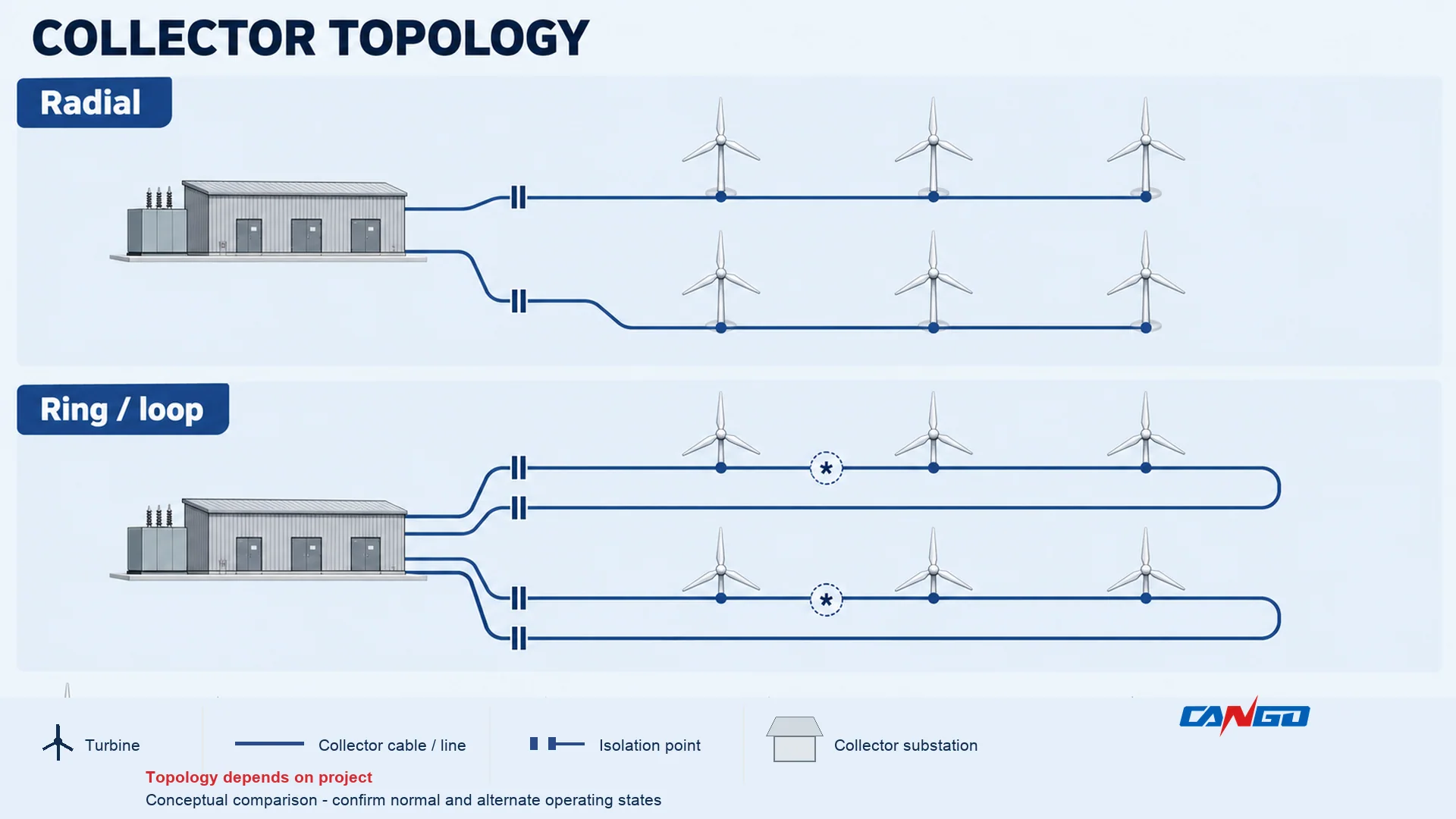
Radial and ring or loop arrangements are different starting points, not a simple good-versus-better ranking. A radial feeder has one electrical path from the collector node to the far end of a branch. A ring or loop provides another path or connection at the collector end, but that does not automatically mean uninterrupted supply or automatic transfer. Normal and alternate switching states, isolation points, protection and operating rules still need to be defined.
| Decision point | Radial collector | Ring or loop collector |
|---|---|---|
| Path from collector node | One electrical path per branch, with the far end terminating at a turbine or equipment point | A cable or line route may return from the far end to the collector end, forming a loop |
| Switching and isolation | Plan isolation at the collector end and at any project-defined sectionalising point | Plan switching and isolation at the loop ends and at each approved sectionalising point |
| Fault behaviour | A fault can affect the complete branch unless the approved scheme isolates a section | The additional path changes available fault paths and protective coordination; it does not remove fault risk |
| Maintenance or outage flexibility | Flexibility follows the actual isolation, earthing and operating scheme | May offer an alternate path in defined operating states, but only when studies, interlocks and procedures permit it |
| Cable or line quantity and routing | Fewer end-to-end paths may reduce route complexity, subject to voltage-drop and thermal checks | More route or equipment connections can increase cable, joint, termination and isolation scope |
| Suitable starting condition | The branch length, losses, voltage profile, fault coordination and outage plan fit a one-ended arrangement | The project has a credible switching and protection scheme for the loop and needs the flexibility that the scheme can actually provide |
The lower path count of a radial arrangement is not automatically cheaper over the installed life. The loop’s alternative connection is not automatically a redundancy guarantee. Compare complete installed scope, study results, outage strategy, protection complexity and the owner’s operation and maintenance capability.
Medium-voltage switching, protection and earthing
MV switchgear provides a controlled boundary between the collector, transformer and other station circuits. The equipment arrangement must make the required functions possible, but the enclosure alone does not define them. Confirm the switching devices, isolation and earthing provisions, interlocks, cable interfaces, protection devices, metering, control power and communication interfaces for the offered configuration.
IEC 62271-200:2021 covers prefabricated metal-enclosed alternating-current switchgear and controlgear assemblies above 1 kV through 52 kV and up to 60 Hz, for indoor and outdoor installations (IEC, 2021). That published scope helps frame the equipment class; it does not specify this project’s voltage, fault duty, protection settings or complete design.
Protection has to see both individual and aggregate behaviour
Wind-plant collector fault protection and coordination must consider the short-circuit behaviour of individual wind-turbine generators as well as the aggregate plant contribution, along with interconnection protection, security, reliability and safety (NREL/ORNL, 2010).
That is why a protection review cannot be reduced to comparing a fuse with a breaker in isolation. It must cover:
- Fault contributions from the turbine type and quantity, collector transformers and project transformer.
- The fault level and duration at every switchgear location.
- Current-transformer location, accuracy and saturation considerations.
- Selectivity between turbine, feeder, transformer and grid-side protection.
- Sensitivity to the actual operating states, including any intended alternate feed path.
- Security against unnecessary trips and reliability for the faults that must be cleared.
- Earthing, insulation coordination and overvoltage protection as part of the same equipment review.
- Metering and control power that remain valid for the required operating states.
Our RMU transformer-protection comparison helps frame the circuit-breaker and fuse decision, but each arrangement still needs a reviewed study and approved settings.
Define SCADA and control power across the same boundary
Wind-plant SCADA and control functions include turbine controls, plant-level control, intelligent electronic devices (IEDs) and communication systems (NREL/ORNL, 2011). Those functions should appear on the interface schedule rather than being treated as an optional add-on after the power equipment is selected.
For an MV switchgear enquiry, identify the signals, devices and responsibilities that must be coordinated:
- Switch position, fault or trip indication, alarm and status signals needed by the plant controller.
- Protection IEDs, metering devices and the communication protocol or interface required at each boundary.
- Control-power source, changeover arrangement and the behaviour required after loss of normal auxiliary supply.
- Time synchronization, event recording and cybersecurity responsibilities where the project defines them.
- Local operation, remote operation and authority transfer between turbine, plant and grid operators.
The packet shown in the first diagram is not enough to define these functions. Request the device schedule, communication interface and control-power arrangement for the exact offered equipment. IEC 61400-1:2019 gives wind-turbine design requirements that include control and protection functions and internal electrical systems within the turbine scope (IEC, 2019); it does not define the wind-farm collector or project substation.
Treat earthing and overvoltage as interfaces, not assumptions
Wind-plant grounding, overvoltage protection and insulation coordination must be considered together. Surge arresters can protect collector-system insulation from transient overvoltages, but their application is constrained by maximum operating voltage and temporary overvoltage levels (NREL/ORNL, 2009).
Require the responsible project engineer to define the earthing approach for:
- Turbine and collector equipment.
- Cable shields, metallic sheaths, armouring and line hardware.
- Transformer tanks, switchgear enclosures and cable terminations.
- Station fences, structures and separately owned equipment at the interconnection.
Do not infer a safe touch-voltage criterion, electrode length or clearance from this conceptual article. Ask for the study basis, the assumptions and the equipment interfaces that the supplier must meet.
Step-up transformers and the grid interface
Wind-farm transformers have two broad functional roles. A turbine or package transformer, where present, raises the turbine’s terminal voltage to the collector level. A project step-up transformer links the collector voltage to the grid-side voltage. Some projects use intermediate equipment or multiple stages; it is unsafe to assume one fixed arrangement.
The application of a wind-plant power transformer includes winding configuration, MVA rating, impedance, losses, on-load tap-changing and redundancy (NREL/ORNL, 2010). These are connected decisions. A transformer chosen only by its nameplate ratio may not meet the voltage-control, fault-duty, fault-coordination or operating requirements of the wider plant.
IEC 60076-1:2011 provides general requirements for power transformers within its scope (IEC, 2011). The standard reference does not replace a project specification, impedance study or acceptance of the complete installation.
| Interface | Inputs the wind-farm side should provide or confirm | Requirements to obtain from the grid side or owner |
|---|---|---|
| Point of interconnection | Project layout, expected real and reactive power, collector and transformer data, proposed operating states | Nominal and maximum/minimum voltage, frequency conditions, fault level, protection and metering requirements |
| Transformer interface | Collector voltage, equipment rating basis, transformer role, earthing and control requirements | Voltage ratio, winding configuration, impedance, losses, tap strategy, cooling and redundancy requirements |
| MV switchgear | Feeder schedule, current and fault study, isolation and earthing scheme, communications | Switching, protection, interlocking, indication, access and operation requirements at the boundary |
| Protection and control | Collector IED data, communication architecture, control power and plant control responsibilities | Grid-operator signals, protection interfaces, records and operating authority |
| Metering and commercial boundary | Proposed metering point, circuit ownership and installation access | Revenue or check metering requirements, accuracy class, data route and inspection access |
Use transformer impedance and short-circuit current to prepare the technical discussion, and power-transformer project information to assemble the specification inputs. Neither substitutes for the electrical studies or the interconnection agreement.
Define who owns and operates each boundary
Draw ownership, construction responsibility and operating authority as separate attributes. One party may own an asset while another operates it; an EPC contractor may install equipment that the utility commissions; or a collector system may cross land or waters subject to another agreement. Those differences matter for isolation, access, spare parts, test records and emergency response.
At the grid interface, obtain the approved point of isolation, the responsibility for earthing and tagging, and the method for proving dead before work. Do not rely on a generic statement that the equipment is “utility-approved” or “SIL-rated” unless the exact function, standard and evidence are stated.
Design for the outdoor environment and maintenance reality
Wind farms expose equipment to conditions that may include wind-driven rain, dust, condensation, salt or other contamination, wide temperature variation, vibration during transport and restricted access for lifting. The correct specification responds to the actual site and equipment location. An indoor or outdoor designation alone is not an environmental qualification.
Use the site conditions to interrogate the offer:
- Enclosure ingress, corrosion and condensation protection, including the project’s acceptance criteria and supporting evidence.
- Cable-entry orientation and sealing, drainage, ventilation or pressure relief where the design needs them.
- Transformer cooling, oil containment and separation requirements where applicable.
- Access for operation, inspection, testing and replacement, including door swings and lifting paths.
- Isolation and earthing points that can be reached under the approved site procedure.
- Environmental and safety requirements that apply to the location, including any coastal, seismic, fire or flood exposure identified by the project.
- Spares, special tools, diagnostic access and maintenance information needed for the intended operating model.
Ask for the general arrangement drawing and the maintenance concept, not only a front elevation. Verify that the enclosure can be placed, connected, inspected and maintained without relying on an assumed clearance or temporary arrangement that the site cannot provide.
Match the CANGO RMU family to a defined duty
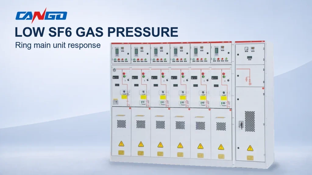
CANGO’s medium-voltage switchgear range includes several MV ring-main-unit families. The mapping below is a starting point for a project enquiry, not a claim that any model is certified for wind farms or suitable for every collector duty. The actual voltage, current, fault, environmental, protection and configuration requirements must be checked against the selected model’s current documentation.
| CANGO family | Published application description | Conditional role in a wind-farm enquiry |
|---|---|---|
| HXGN17-12 | Compact 12 kV, 50 Hz fixed metal-enclosed RMU for receiving, distributing and protecting three-phase power, with ring-network, terminal-distribution and prefabricated-substation applications | Consider when the project’s verified voltage and frequency fit the model and a compact ring or terminal arrangement is required |
| XGN15-12 | AC metal-enclosed RMU for industrial and civil cable ring networks and supply terminals, including small substations and switching stations | Consider for a defined cable-ring or supply-terminal scheme after the collector and station interfaces are fixed |
| SRM-12 | 12 kV gas-insulated RMU described for 6 kV and 10 kV systems, urban and rural distribution and compact substations, with modular switching and protection | Consider only when the actual system voltage and required compact arrangement match the offered configuration |
| GTXGN-12 | Sealed solid-insulated 12 kV RMU using vacuum switching and epoxy-resin insulation, described for cable ring networks and distribution terminals | Consider when the verified cable-ring or terminal duty and project environment fit the offered solid-insulated configuration |
Do not select a family from the words “ring main” alone. Send the single-line diagram, voltage and frequency, continuous and short-time current requirements, fault level, earthing arrangement, protection and metering scope, service environment, cable interface and required operating states. Ask CANGO to state which values apply to the exact offered configuration and which evidence accompanies the quotation.
The utility-distribution MV switchgear guide provides a wider equipment-selection context. It does not set a wind-farm collector design.
Prepare the RFQ before comparing prices
An equipment quotation is only comparable when every bidder prices the same functional scope. Use the following input checklist to reduce clarification cycles.
| RFQ input | What to provide |
|---|---|
| Project basis | Site location, onshore or offshore context, project stage, applicable standards and required approval process |
| Single-line diagram | Turbine or package transformers, collector feeders, bus sections, step-up transformer, point of interconnection and all known interfaces |
| Electrical duty | Nominal and maximum voltage, frequency, continuous current, fault level and duration, and the study assumptions used |
| Topology and operation | Radial or ring/loop arrangement, normal and alternate states, isolation points, earthing scheme and operating authority |
| Protection and control | Required protective functions, metering, current or voltage transformers, IED interfaces, SCADA, control power and communications |
| Equipment environment | Indoor or outdoor location, ambient and site conditions, enclosure requirements, cable entry and access constraints |
| Transformer data | Role, voltage ratio, winding configuration, rating basis, impedance, losses, taps, cooling, earthing and redundancy |
| Physical interfaces | General arrangement, foundation or support data, cable or line terminations, lifting and replacement route, and interface drawings |
| Verification and documentation | Applicable standards, type or routine test evidence for the offered equipment, operating instructions and maintenance information |
| Commercial scope | Supply boundary, spares, transport, site services, inspection, testing, commissioning support and responsible parties |
For any item that is unknown, state the assumption and who must confirm it. A clean RFQ does not pretend that an open interface is resolved. It makes the open item visible so that the technical and commercial offers can be compared responsibly.
Where an auxiliary low-voltage assembly is included, identify it as a separate equipment boundary. IEC 61439-2:2020 gives specific requirements for low-voltage power switchgear and controlgear assemblies within its defined scope, in conjunction with the general rules of Part 1 (IEC, 2020). The reference does not qualify the MV switchgear, transformer or complete wind-farm installation.
Send the electrical single-line diagram, turbine and transformer data, collector layout, study basis, grid-interface requirements and proposed operating states to CANGO for an MV equipment review. Include the project location and required standards so that the response can distinguish a preliminary configuration discussion from an offer against a defined scope.
References
- NREL — Equivalencing the Collector System of a Large Wind Power Plant, OSTI record and abstract, 2006.
- NREL/ORNL — Design and Application of Cables and Overhead Lines in Wind Power Plants, OSTI record and abstract, 2010.
- NREL/ORNL — Wind Plant Collector System Fault Protection and Coordination, OSTI record and abstract, 2010.
- NREL/ORNL — Power Transformer Application for Wind Plant Substations, OSTI record and abstract, 2010.
- NREL/ORNL — Wind Power Plant Grounding, Overvoltage Protection, and Insulation Coordination, OSTI record and abstract, 2009.
- NREL/ORNL — Wind Power Plant SCADA and Controls, OSTI record and abstract, 2011.
- NREL/ORNL — Harmonics and Resonance Issues with Wind Plants, OSTI record and abstract, 2011.
- IEC — IEC 62271-200:2021, official scope summary; the publication page identifies the consolidated version with the 2024 amendment.
- IEC — IEC 60076-1:2011, official scope summary.
- IEC — IEC 61439-2:2020, official scope summary for low-voltage power switchgear and controlgear assemblies.
- IEC — IEC 61400-1:2019, official scope summary for wind-turbine design requirements.