Utility distribution switchgear should be specified from its position in the network and its required operating states, not from voltage class or a familiar cabinet model alone. A primary-substation incomer, an outgoing feeder, a bus section, a ring-network sectionalizing point, and a distribution-transformer supply unit perform different switching, protection, measurement, automation, and restoration duties.
The practical design sequence is to map the source-to-load architecture, define normal and contingency states, establish load and fault duties, assign every functional unit, specify protection and remote-control interfaces, account for site and maintenance conditions, and then compare offers against one common schedule. Local utility rules and the approved network study remain authoritative.
Start with the utility network boundary
A medium-voltage utility network normally contains several equipment boundaries. Power enters from a grid source or upstream transformer, passes through primary-substation switchgear, travels along overhead or underground feeders, reaches switching or ring-main nodes, and supplies distribution transformers before entering the low-voltage network.
The switchgear specification must identify who owns and controls each boundary. The utility, EPC contractor, civil contractor, protection integrator, SCADA team, cable supplier, and equipment manufacturer may all have different deliverables. A technically complete inquiry defines those interfaces instead of asking one switchgear supplier to infer the whole network.
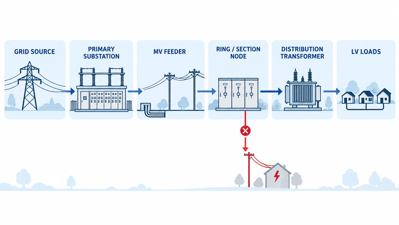
Three network arrangements that change the switchgear duty
Radial feeders
In a radial arrangement, a load point has one normal supply path. The architecture is straightforward, but the consequence of an upstream fault or planned outage may cover every downstream customer until the fault is isolated and supply is restored. The specification should identify sectionalizing points, normally open ties if any, fault indication, remote-control needs, and the permitted restoration procedure.
A radial feeder does not automatically mean simple protection. Long feeders, distributed generation, transformer inrush, earth-fault behavior, and changing source conditions can affect the required study. Switchgear suppliers need the protection philosophy and instrument-transformer data, while the utility or protection engineer retains responsibility for coordination and settings unless explicitly included.
Open-ring or loop networks
An open ring has more than one physical path but normally operates with a defined open point. After a faulted section is identified and isolated, an approved switching sequence may restore healthy sections from the alternate direction, subject to feeder capacity, voltage, protection, interlocking, and utility operating rules.
Ring-main switchgear therefore needs a module schedule, not just the label “RMU.” Each way may perform cable switching, transformer protection, metering, earthing, bus sectionalizing, or circuit-breaker protection. State the normal open point, permitted back-feed direction, cable test method, remote operation requirement, and future extension plan.
Sectionalized or double-bus primary substations
Primary substations may use single-bus, sectionalized-bus, double-ended, or other utility-approved arrangements. Incomers, bus sections, bus couplers, outgoing feeders, measurement panels, station-service circuits, and spare ways must be shown on the single-line diagram.
The presence of two sources or a bus coupler does not prove that parallel operation is allowed. The project must state normal breaker positions, transfer philosophy, synchronizing requirements where applicable, interlocks, fault-level implications, transformer compatibility, and the protection logic for every permitted operating state.
Match switchgear type to the network node
No single construction is optimal for every point in a utility network.
| Network position | Typical functional need | Equipment direction to evaluate | Data that decides the choice |
|---|---|---|---|
| Primary substation incomer or bus | High-duty switching, bus protection interfaces, metering, control, defined maintenance access | Metal-enclosed circuit-breaker switchgear; withdrawable or fixed according to utility policy | System voltage, bus current, fault duty, bus scheme, protection, continuity and access requirements |
| Primary outgoing feeder | Cable or overhead-line protection, reclosing or sectionalizing philosophy, CT/VT and SCADA interfaces | Circuit-breaker feeder functional unit | Feeder type and length, fault study, earthing, relay functions, operating sequence, communications |
| Ring or sectionalizing node | Load switching, fault isolation, earthing, optional remote operation and extensibility | Ring-main or compact metal-enclosed switchgear | Module schedule, load current, fault making/withstand duty, cable interfaces, automation and environment |
| Distribution-transformer supply | Transformer switching and protection | Switch-fuse or circuit-breaker functional unit as approved by the protection study | Transformer rating, inrush, fault duty, fuse/relay coordination, cable and earthing arrangement |
| Network tie or normally open point | Controlled transfer or restoration path | Load-break switch or circuit-breaker function according to required duty | Normal state, transfer current, fault duty, interlocks, remote-control logic and permitted parallel conditions |
| Future feeder or extension | Expansion without invalidating the existing lineup | Spare functional unit, fitted spare, or engineered extension interface | Forecast load, bus rating, physical space, extension side, outage plan and verification route |
The metal-clad versus metal-enclosed guide explains why construction labels are not substitutes for ratings, IEC classifications, or test evidence. For the wider technology selection, use the medium-voltage switchgear selection guide.
Ratings must cover every credible operating state
IEC 62271-200:2021+A1:2024 applies to prefabricated AC metal-enclosed switchgear and controlgear above 1 kV and up to and including 52 kV, for indoor or outdoor installation and service frequencies up to 60 Hz. IEC 62271-1:2017+A1:2021 provides common specifications for AC switchgear and controlgear above 1,000 V. The project should state the required standards, editions, national adoptions, utility specifications, and deviations.
For each bus section and functional unit, keep these values separate:
- rated voltage and insulation level;
- rated frequency;
- busbar and feeder rated normal current;
- prospective short-circuit current at the installation point;
- rated short-time withstand current and duration;
- rated peak withstand current;
- circuit-breaker breaking and making duties where applicable;
- load-break, fault-making, or switch-fuse duties for the selected functional unit;
- internal arc classification, loss of service continuity, partition class, and degree of protection when required;
- auxiliary and control supply ratings.
Calculate fault duty for the permitted network states, including alternate sources, closed ties, parallel transformers, embedded generation, and future reinforcement where those states are allowed. A higher nameplate number is not a substitute for a documented study and complete current path.
Service conditions also belong in the rating basis. Altitude, ambient temperature, solar exposure, humidity, condensation, flooding risk, dust, salt, pollution, corrosion, seismic conditions, wildlife, ventilation, and indoor/outdoor installation can change the required enclosure or design. The supplier should identify any derating or special provision against the declared conditions.
Protection and measurement follow feeder duty
Utility feeder protection is a system function, not a breaker accessory list. The protection engineer determines the required functions and settings from the network study, earthing method, feeder type, source behavior, selectivity objective, operating states, and utility rules.
The switchgear inquiry should nevertheless define the interfaces clearly:
- feeder and bus current transformers or sensors, including ratios, cores, classes, burdens, and terminal arrangements;
- voltage transformers or sensors, fusing and isolation where required;
- protection relay functions and approved device family if mandated;
- trip and close circuits, supervision, anti-pumping, lockout, and interlocking interfaces;
- breaker operating duty and any reclosing requirement;
- fault-passage indication or directional indication at secondary nodes;
- metering accuracy and revenue-metering boundaries where applicable;
- disturbance records, sequence-of-events data, and time synchronization requirements;
- secondary injection, test-switch, and commissioning interfaces.
Do not issue final relay settings from generic article values. The settings must come from the approved study and must be tested against the actual CT/VT data, breaker timing, communication scheme, and network configuration.
Build automation around use cases, not protocol names
Remote control adds value only when the utility defines what operators need to observe and command. Typical use cases include feeder status and alarms, fault indication, remote open/close control, restoration switching, load measurement, condition alarms, and transfer coordination.
IEC TR 61850-90-6:2018 addresses information exchange for distribution-automation applications within medium-voltage network automation and notes that distribution automation differs among countries, regions, and utilities. IEC 61850-5:2013+A1:2022 addresses communication requirements for functions and device models in power utility automation systems. Referencing IEC 61850 does not, by itself, define the required data set, architecture, interoperability profile, cybersecurity controls, or acceptance tests.
Specify the automation boundary through an input/output and communication schedule:
| Interface group | Minimum project definition |
|---|---|
| Status and alarms | Breaker/switch positions, earthing position, spring or mechanism status, protection trips, DC supply alarms, local/remote state |
| Commands | Authorized open/close or transfer commands, control authority, interlocks, select-before-operate logic where required |
| Measurements | Current, voltage, power, energy, frequency, power factor, fault records, and accuracy requirements |
| Communications | Protocol, physical medium, network topology, addressing, time synchronization, redundancy, gateway responsibility |
| Control power | DC/AC voltage, autonomy, charger/battery boundary, trip/close energy, monitoring and distribution |
| Testing and handover | Point list, signal simulation, end-to-end tests, configuration files, backups, drawings, passwords and change-control records |
The utility’s cybersecurity, telecom, and operational-technology requirements should be provided separately and reconciled with the equipment scope.
Design for isolation, restoration, and maintenance
Reliability is created by the whole system: network topology, protection selectivity, switching points, alternate capacity, fault location, communications, spare equipment, operating procedures, crew response, and maintainable access. A switchgear label cannot guarantee a restoration time.
For each planned or faulted condition, ask four questions:
- What section must be de-energized and earthed?
- Which healthy sections are allowed to remain energized?
- What alternate path and capacity are available for restoration?
- What local or remote switching sequence is authorized and interlocked?
Then translate the answers into bus sections, isolating points, earthing facilities, LSC and internal-arc requirements where applicable, accessible sides, cable-test access, remote operation, spare parts, and room layout. Safe isolation, proving dead, earthing, access, and energized work remain governed by utility procedures and local regulations.
A six-stage utility switchgear specification workflow
1. Define network role and ownership
Identify the substation or feeder node, source and load boundaries, utility/EPC/supplier scope, system voltage, frequency, earthing method, and target in-service date. Attach the approved or design-stage single-line diagram.
2. Document normal and contingency states
List normal open and closed devices, ties, alternate feeds, permitted parallel states, transfer sequences, isolation points, and future configurations. This prevents a supplier from rating equipment for only one operating diagram.
3. Establish load and fault duties
Provide bus and feeder currents, load profile, demand growth, fault current and clearing duration at each node, transformer and generator contributions, and any duty affected by distributed energy resources.
4. Assign functional units and interfaces
Convert the single-line diagram into incomers, feeders, bus sections, bus couplers, measurement panels, transformer-protection units, station-service circuits, spare ways, and future spaces. Define cables, bus ducts, CT/VT, protection, control power, metering, communications, and civil interfaces.
5. Define classifications, site conditions, and evidence
State applicable standards and utility specifications, service conditions, enclosure and accessibility requirements, continuity and internal-arc classifications, routine tests, required type-test evidence, drawings, manuals, and configuration records.
6. Normalize offers and deviations
Require every bidder to complete the same schedule. Separate compliant items, proposed alternatives, exclusions, provisional selections, utility approvals, and information still required. Compare price only after the technical scope is aligned.
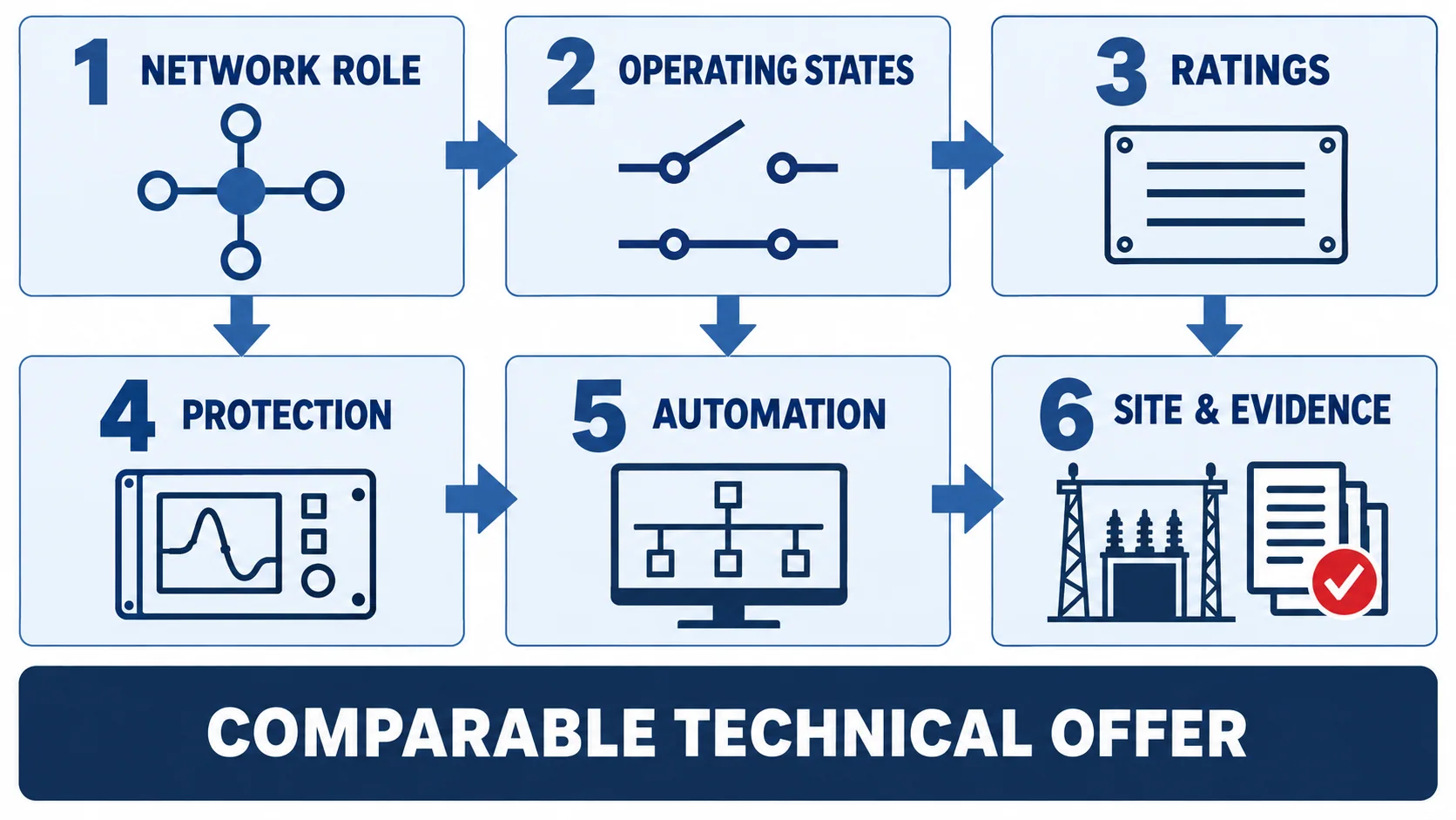
Utility distribution switchgear RFQ checklist
Include at least the following in the inquiry package:
- single-line diagram and normal/contingency operating narrative;
- nominal and highest system voltage, frequency, and earthing method;
- bus and feeder currents, load schedule, forecast growth, and future feeders;
- short-circuit study results with current, duration, source configuration, and study date;
- functional-unit and panel schedule;
- protection philosophy, CT/VT schedule, relay I/O, and approved-device constraints;
- control supply, interlocking, local/remote operation, RTU/SCADA, protocol, and point list;
- LSC, partition, IAC, accessibility, IP/enclosure, and cable-test requirements where applicable;
- indoor/outdoor environment, altitude, temperature, humidity, pollution, corrosion, seismic, and ventilation data;
- cable sizes, number per phase, entry direction, termination and earthing interfaces;
- room layout, access clearances, pressure-relief route, transport sections, and foundation data;
- required drawings, compliance schedule, test evidence, routine-test reports, manuals, training, spares, and document language;
- quantity, delivery destination, packaging constraints, and required schedule.
Use the MV switchgear single-line diagram guide to identify missing functional data, then use the quotation checklist to organize the final inquiry documents.
Where CANGO equipment families may fit
CANGO’s medium-voltage switchgear category includes KYN28-12, KYN28-24, and KYN61-40.5 armored removable AC metal-enclosed families for project-specific primary distribution review. The catalog also includes compact secondary-distribution families such as GTXGN-12 solid-insulated ring main units and SRM-12 gas-insulated ring main units.
These product families identify possible starting points only. The final configuration must follow the utility standard, approved single-line diagram, load and fault studies, protection and automation philosophy, environmental conditions, layout, and evidence requirements. Product-family availability does not establish compliance, IAC, LSC, IP, communication capability, or utility approval for a particular project.
Send CANGO the single-line diagram, operating states, voltage and frequency, feeder schedule, load and fault duties, protection and automation requirements, utility standards, site conditions, layout, quantity, destination, and required documents for a configuration review.