Power Transformer
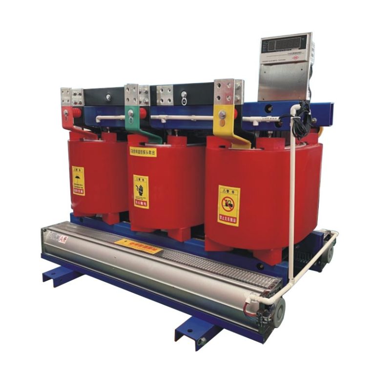
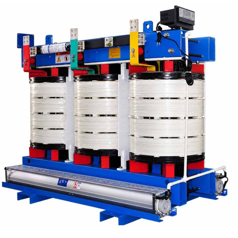
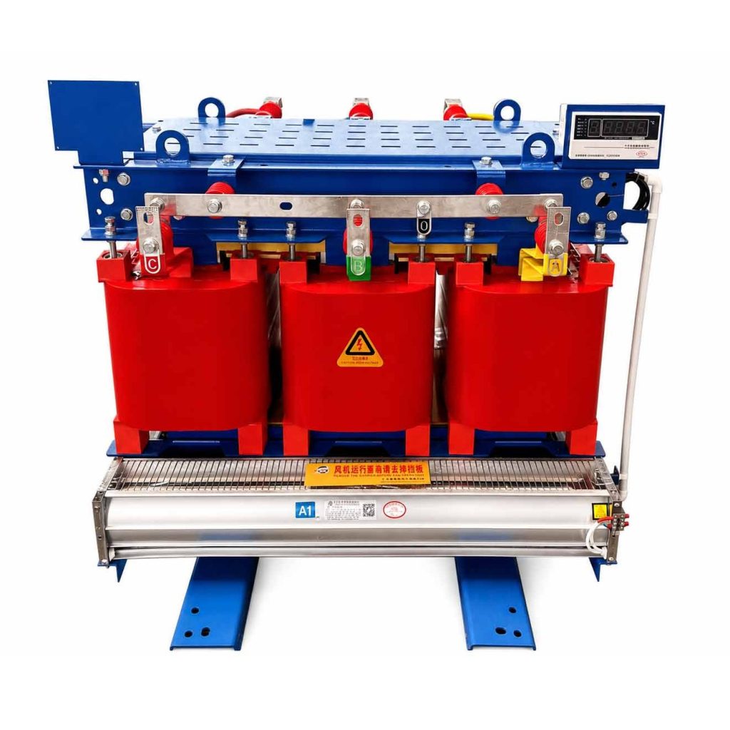
SCBH15 Amorphous Alloy Dry-Type Transformer
Model SCBH15
CANGO supplies SCBH15 Dry-Type Amorphous Alloy Iron Core Power Transformer for commercial and industrial electrical projects. Send rated data, drawings.
Share your rated data, quantity and project requirements.
Project configuration reviewTechnical documentation support
Product Overview
SCBH15 dry-type amorphous alloy iron core power transformer combines a dry-type transformer arrangement with an amorphous alloy core. It is commonly used for commercial and industrial electrical projects and indoor distribution systems, with the final selection based on rated data, drawings, and site conditions.
utilities, EPC contractors, transformer distributors, industrial project owners, and electrical engineering companies can request configuration review for dry type amorphous alloy transformer. Please send capacity, voltage combination, tap range, connection group, cooling or insulation type, loss data, impedance, and installation environment, quantity, destination, and any project standard requirements for quotation.
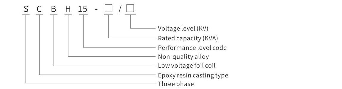
Model and Meaning
Technical Specifications
Main Product Performance Parameters of SCBH15 10 kV Amorphous Alloy Dry-Type Transformer
| Model | Rated capacity (kVA) | Connection group | High voltage (kV) | Tap range (%) | Low voltage (kV) | No-load current (%) | No-load loss (W) | Load loss B-class (W) | Load loss F-class (W) | Load loss H-class (W) | Short-circuit impedance (%) |
|---|---|---|---|---|---|---|---|---|---|---|---|
| SCBH15-30 | 30 | Dyn11 / Yyn0 | 6 / 6.3 / 6.6 / 10 / 10.5 / 11 | +/-2.5% / +/-5%; selected capacities +/-2 x 2.5% / +/-5% | 0.4 | 1.6 | 70 | 670 | 710 | 760 | 4 |
| SCBH15-50 | 50 | Dyn11 / Yyn0 | 6 / 6.3 / 6.6 / 10 / 10.5 / 11 | +/-2.5% / +/-5%; selected capacities +/-2 x 2.5% / +/-5% | 0.4 | 1.4 | 90 | 940 | 1000 | 1070 | 4 |
| SCBH15-80 | 80 | Dyn11 / Yyn0 | 6 / 6.3 / 6.6 / 10 / 10.5 / 11 | +/-2.5% / +/-5%; selected capacities +/-2 x 2.5% / +/-5% | 0.4 | 1.3 | 120 | 1290 | 1380 | 1480 | 4 |
| SCBH15-100 | 100 | Dyn11 / Yyn0 | 6 / 6.3 / 6.6 / 10 / 10.5 / 11 | +/-2.5% / +/-5%; selected capacities +/-2 x 2.5% / +/-5% | 0.4 | 1.2 | 130 | 1480 | 1570 | 1690 | 4 |
| SCBH15-125 | 125 | Dyn11 / Yyn0 | 6 / 6.3 / 6.6 / 10 / 10.5 / 11 | +/-2.5% / +/-5%; selected capacities +/-2 x 2.5% / +/-5% | 0.4 | 1.1 | 150 | 1740 | 1850 | 1980 | 4 |
| SCBH15-160 | 160 | Dyn11 / Yyn0 | 6 / 6.3 / 6.6 / 10 / 10.5 / 11 | +/-2.5% / +/-5%; selected capacities +/-2 x 2.5% / +/-5% | 0.4 | 1.1 | 170 | 2000 | 2130 | 2280 | 4 |
| SCBH15-200 | 200 | Dyn11 / Yyn0 | 6 / 6.3 / 6.6 / 10 / 10.5 / 11 | +/-2.5% / +/-5%; selected capacities +/-2 x 2.5% / +/-5% | 0.4 | 1 | 200 | 2370 | 2530 | 2710 | 4 |
| SCBH15-250 | 250 | Dyn11 / Yyn0 | 6 / 6.3 / 6.6 / 10 / 10.5 / 11 | +/-2.5% / +/-5%; selected capacities +/-2 x 2.5% / +/-5% | 0.4 | 1 | 230 | 2590 | 2760 | 2960 | 4 |
| SCBH15-315 | 315 | Dyn11 / Yyn0 | 6 / 6.3 / 6.6 / 10 / 10.5 / 11 | +/-2.5% / +/-5%; selected capacities +/-2 x 2.5% / +/-5% | 0.4 | 0.9 | 280 | 3270 | 3470 | 3730 | 4 |
| SCBH15-400 | 400 | Dyn11 / Yyn0 | 6 / 6.3 / 6.6 / 10 / 10.5 / 11 | +/-2.5% / +/-5%; selected capacities +/-2 x 2.5% / +/-5% | 0.4 | 0.8 | 310 | 3750 | 3990 | 4280 | 4 |
| SCBH15-500 | 500 | Dyn11 / Yyn0 | 6 / 6.3 / 6.6 / 10 / 10.5 / 11 | +/-2.5% / +/-5%; selected capacities +/-2 x 2.5% / +/-5% | 0.4 | 0.8 | 360 | 4590 | 4880 | 5230 | 4 |
| SCBH15-630 | 630 | Dyn11 / Yyn0 | 6 / 6.3 / 6.6 / 10 / 10.5 / 11 | +/-2.5% / +/-5%; selected capacities +/-2 x 2.5% / +/-5% | 0.4 | 0.7 | 420 | 5530 | 5880 | 6290 | 4 |
| SCBH15-630 | 630 | Dyn11 / Yyn0 | 6 / 6.3 / 6.6 / 10 / 10.5 / 11 | +/-2.5% / +/-5%; selected capacities +/-2 x 2.5% / +/-5% | 0.4 | 0.7 | 410 | 5610 | 5960 | 6400 | 6 |
| SCBH15-800 | 800 | Dyn11 / Yyn0 | 6 / 6.3 / 6.6 / 10 / 10.5 / 11 | +/-2.5% / +/-5%; selected capacities +/-2 x 2.5% / +/-5% | 0.4 | 0.7 | 480 | 6550 | 6960 | 7460 | 6 |
| SCBH15-1000 | 1000 | Dyn11 / Yyn0 | 6 / 6.3 / 6.6 / 10 / 10.5 / 11 | +/-2.5% / +/-5%; selected capacities +/-2 x 2.5% / +/-5% | 0.4 | 0.6 | 550 | 7650 | 8130 | 8760 | 6 |
| SCBH15-1250 | 1250 | Dyn11 / Yyn0 | 6 / 6.3 / 6.6 / 10 / 10.5 / 11 | +/-2.5% / +/-5%; selected capacities +/-2 x 2.5% / +/-5% | 0.4 | 0.6 | 650 | 9100 | 9690 | 10370 | 6 |
| SCBH15-1600 | 1600 | Dyn11 / Yyn0 | 6 / 6.3 / 6.6 / 10 / 10.5 / 11 | +/-2.5% / +/-5%; selected capacities +/-2 x 2.5% / +/-5% | 0.4 | 0.6 | 760 | 11050 | 11730 | 12580 | 6 |
| SCBH15-2000 | 2000 | Dyn11 / Yyn0 | 6 / 6.3 / 6.6 / 10 / 10.5 / 11 | +/-2.5% / +/-5%; selected capacities +/-2 x 2.5% / +/-5% | 0.4 | 0.5 | 1000 | 13600 | 14450 | 15560 | 6 |
| SCBH15-2500 | 2500 | Dyn11 / Yyn0 | 6 / 6.3 / 6.6 / 10 / 10.5 / 11 | +/-2.5% / +/-5%; selected capacities +/-2 x 2.5% / +/-5% | 0.4 | 0.5 | 1200 | 16150 | 17170 | 18450 | 6 |
| SCBH15-1600 | 1600 | Dyn11 / Yyn0 | 6 / 6.3 / 6.6 / 10 / 10.5 / 11 | +/-2.5% / +/-5%; selected capacities +/-2 x 2.5% / +/-5% | 0.4 | 0.6 | 760 | 12280 | 12960 | 13900 | 8 |
| SCBH15-2000 | 2000 | Dyn11 / Yyn0 | 6 / 6.3 / 6.6 / 10 / 10.5 / 11 | +/-2.5% / +/-5%; selected capacities +/-2 x 2.5% / +/-5% | 0.4 | 0.5 | 1000 | 15020 | 15960 | 17110 | 8 |
| SCBH15-2500 | 2500 | Dyn11 / Yyn0 | 6 / 6.3 / 6.6 / 10 / 10.5 / 11 | +/-2.5% / +/-5%; selected capacities +/-2 x 2.5% / +/-5% | 0.4 | 0.5 | 1200 | 17760 | 18890 | 20290 | 8 |
Installation Dimensions / Drawing
ForSCBH15, confirm the capacity-specific outline dimensions, installation base, terminal position, cooling clearance, and lifting / handling requirements. Use the confirmed technical table, project drawing, and site installation plan as the final dimensional reference before ordering or installation.
Applications
SCBH15 is mainly selected for commercial and industrial electrical projects and indoor distribution systems. The final application should match the confirmed dry type amorphous alloy transformer, rated data, and site installation conditions.
- Commercial and industrial electrical projects
- Indoor distribution systems
- Projects requiring dry-type amorphous alloy core transformers
Ordering Instructions / Information Required for Quotation
ForSCBH15, send capacity, voltage combination, tap range, connection group, cooling or insulation type, loss data, impedance, and installation environment, quantity, destination, and the expected delivery schedule. The engineering review will be based on the selected dry type amorphous alloy transformer and project drawing.
ORDERING INSTRUCTIONS
- State the required SCBH15 configuration, quantity, project destination, and intended application.
- Provide capacity, voltage combination, tap range, connection group, impedance, loss data, cooling or insulation type, and installation environment for technical review.
- Confirm the capacity-specific outline dimensions, installation base, terminal position, cooling clearance, and lifting / handling requirements before final production or installation planning.
- List any special environmental, wiring, communication, metering, protection, or component requirements in the inquiry.
EXPLORE THE RANGE
Related equipment