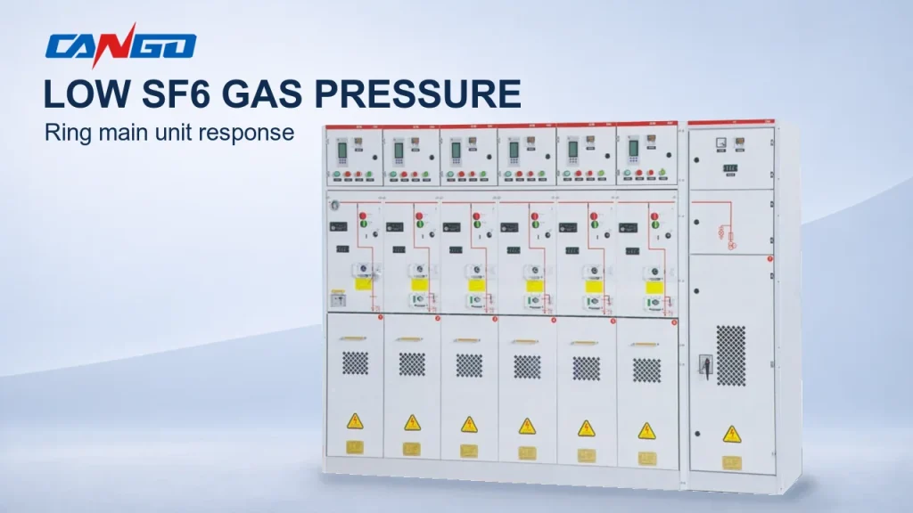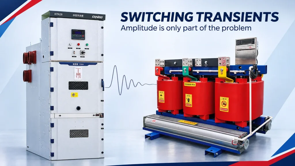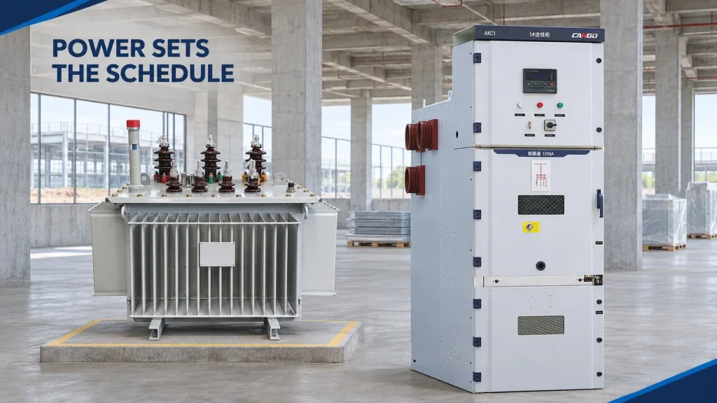
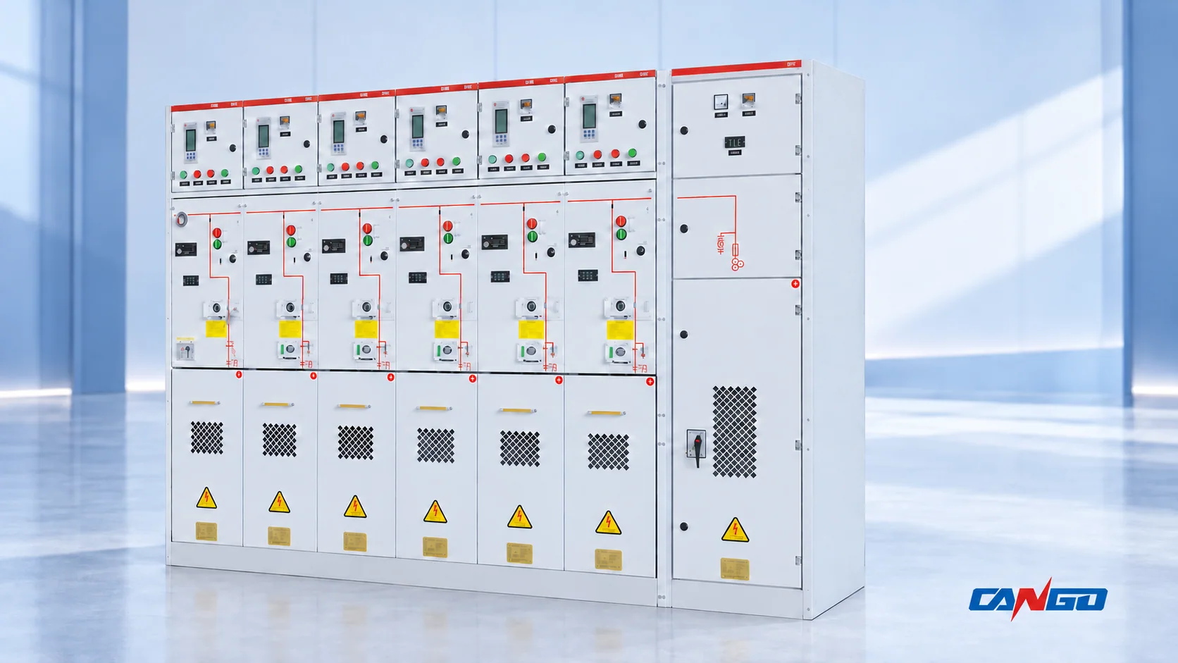
For RMU transformer protection, a switch-fuse combination uses current-limiting fuses and a common three-phase switch. A circuit breaker with a suitable relay provides adjustable protection pickup and timing. Both can be suitable; the choice depends on required low-current and high-current protection, transformer loading, inrush, MV/LV selectivity and operating functions.
A switch-fuse feeder must use an approved combination of switch, fuses and striker-operated tripping. A circuit-breaker feeder must include a suitable sensing, relay and trip chain. Neither the RMU label nor transformer capacity alone proves that the protection covers the project.
The useful comparison is therefore: which conditions must this transformer feeder detect, how will it disconnect all three phases, and what coordination evidence supports the offered scheme?
How the two transformer protection paths work
Switch-fuse: a coordinated three-pole combination
The primary current passes through a switch and current-limiting fuses. When a fuse operates, its striker actuates the common switch mechanism so that the feeder opens in three phases. Schneider’s RM6 instruction sheet describes this striker-initiated three-phase opening.
At high fault currents, the fuses may clear before the switch opens; at other duties, the switch participates in interruption. Fuse selection by nominal current alone therefore does not define the feeder.
IEC 62271-105:2021 covers three-pole functional switch-fuse combinations above 1 kV through 52 kV. The component fuses have their own standard, IEC 60282-1:2020. The combination rating is a separate consideration from an individual fuse’s rating.
Circuit breaker: a relay-controlled interruption path
In a typical circuit-breaker transformer feeder, current transformers or dedicated sensors provide inputs to a relay. The relay evaluates enabled protection functions and sends a trip command to the breaker. The breaker interrupts the primary circuit.
This separates sensing and protection logic from current interruption. It permits an adjustable protection characteristic, provided the selected relay, sensors and trip arrangement support the required duty. Schneider’s MV/LV transformer protection guidance discusses the coordination and low-level fault-detection benefits of a suitable breaker-and-relay scheme.
A vacuum circuit breaker, or VCB, is an interruption device; its name does not specify the complete protection package. Phase overcurrent, earth-fault, thermal, external trip and communications functions must be identified in the offer.
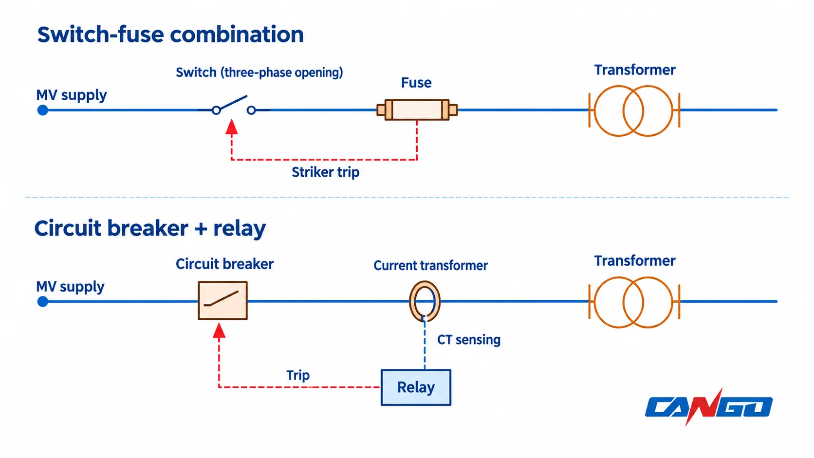
Switch-fuse vs circuit breaker: compare the same duties
Use the same transformer, network and downstream protection data when reviewing the two options.
| Review point | Switch-fuse combination | Circuit breaker with relay |
|---|---|---|
| Detection and trip path | Fuse operation or a specified additional trip function actuates the coordinated switch | Sensors and enabled relay functions command the breaker trip |
| High-current fault duty | Current-limiting fuse performance and combination duty must match the fault study | Breaker interruption rating and total protection clearing time must match the fault study |
| Low-current protection | Check the actual fuse/combination response and any additional detection; do not infer sensitive protection from fuse amperes | Check pickup, sensing accuracy, enabled functions and trip availability at the minimum relevant fault current |
| Inrush | Select fuse characteristics that ride through transformer energization | Select and coordinate relay characteristics or supported inrush logic |
| Transformer overload | Define thermal protection and its alarm/trip interface separately | Confirm that a suitable thermal function or sensor-trip interface is included |
| Downstream selectivity | Demonstrate coordination with the actual LV protective devices | Demonstrate coordination using the actual MV relay and LV device characteristics |
| Restoration after operation | Include approved replacement-fuse availability and the maintenance plan | Include fault investigation, relay records, reset conditions and breaker maintenance requirements |
| Future changes | Recheck approved fuse selection and combination limits | Recheck sensors, setting ranges, duty and the coordination study |
No row establishes a universal winner. For example, requiring remote operation does not automatically exclude a switch-fuse unit, and ordering a VCB does not automatically include remote control. State the required function and verify the offered implementation.
What must be checked in a switch-fuse combination?
Compatibility and thermal loading
The RMU manufacturer’s approved fuse references are the starting point. Confirm voltage, rated current, fuse class, time-current characteristics, dimensions, striker characteristics and permitted heat dissipation in the actual enclosure.
Two fuse links can have the same nominal current and fit the same holder while having different electrical and mechanical characteristics. Schneider’s RM6 fuse compatibility guidance explicitly identifies differences such as time-current characteristics, resistance and striker performance. Dimensional fit alone is not approval for substitution.
The selection also has to tolerate the transformer’s stated load profile and inrush without overheating the fuse compartment. ABB’s SafeRing/SafePlus catalogue treats these as separate fuse-selection checks. Its tables apply to the specified ABB combinations and conditions; they are not a fuse schedule for another manufacturer’s RMU.
Transfer current is not minimum breaking current
These terms describe different boundaries:
- Fuse minimum breaking current is the lower boundary of the fuse’s declared interruption range. A back-up fuse must not be assumed to safely interrupt every current capable of melting its element.
- Combination transfer current is the three-phase symmetrical current at which the fuse and switch exchange interruption duties. It depends on fuse characteristics and the switch’s fuse-initiated opening behavior.
ABB’s fuse catalogue describes the back-up fuse range. Its Medium-voltage fuses Technical Guide, section 4.6 explains transfer-duty coordination.
Under the specified three-phase fault conditions, below the transfer boundary the switch can interrupt the remaining phases after a fuse initiates tripping; above it, the fuses clear the fault before switch opening.
The equipment review must establish that the selected fuse and switch combination remains within its rated transfer duty, including the relevant tolerances. It must also address low-current behavior and the transformer secondary-terminal fault condition, as reflected in ABB’s transformer fuse-selection checks. A fuse’s maximum breaking rating, by itself, does not answer those questions.
Do not use transfer current as a relay pickup setting or substitute it for the fuse minimum breaking current. Ask the supplier for the approved coordination basis for the exact fuse reference and transformer data.
Low fault current and transformer overload need separate answers
A severe terminal short circuit and a developing internal fault can produce very different primary currents. A feeder designed around large fault interruption can still need additional detection at lower currents.
For a dry-type transformer, winding-temperature sensors can provide thermal monitoring, while some internal faults may produce modest line overcurrent. Schneider’s transformer protection guide distinguishes these conditions and explains why appropriate relay protection may be preferred for low-level internal-fault currents. A basic overcurrent relay should not be treated as proof that every incipient winding fault will be detected.
Earth-fault coverage also depends on the network earthing arrangement and the available fault current. Define the minimum earth-fault current that needs detection before evaluating fuse response or relay sensitivity.
Overload is a thermal question as well as a current question. Confirm the permitted loading, transformer temperature monitoring and required alarm or trip action. A thermal striker designed to limit fuse overheating does not, by itself, establish winding-temperature protection for the transformer. Additional temperature or pressure contacts can only protect the feeder if their detection, trip interface and opening duty are included and verified.
The same distinction applies to a VCB offer. The breaker can interrupt following a trip command; a thermal sensor or suitable relay function must first generate that command.
What a circuit-breaker-and-relay offer must prove
Review the complete chain, not just the relay model:
- Measurement: which sensors are supplied, their ratios or operating ranges, and their suitability for the required minimum and maximum currents.
- Protection: which phase, earth-fault, thermal and external-trip functions are supplied and enabled.
- Coordination: the proposed pickup ranges, curves and total clearing behavior against transformer limits and upstream/downstream devices.
- Trip energy: how the relay and trip actuator obtain energy, including startup and operation under the relevant fault conditions.
- Interfaces: temperature contacts, alarms, interlocks and remote commands required by the operating philosophy.
Self-powered protection can reduce dependence on an external auxiliary supply for its specified functions. It still has sensor-current and startup conditions. Schneider’s VIP400 pickup explanation shows why low current and relay pickup time matter. Check the selected relay’s documentation rather than assuming that “self-powered” means every protection and communication function works under every supply condition.
The breaker device requirements and the assembled RMU requirements also remain separate. IEC 62271-100 addresses AC circuit breakers; IEC 62271-200 addresses metal-enclosed switchgear assemblies above 1 kV through 52 kV. Request documents for the offered device and assembly configuration; citing either standard is not evidence that a particular offer meets the project.
Check coordination across six operating conditions
A defensible comparison checks both unwanted operation and failure to operate:
| Condition | Question the coordination review must answer |
|---|---|
| Transformer energization | Will the selected fuse or relay ride through the manufacturer’s inrush envelope? |
| Continuous load and permitted overload | Will the feeder remain within its thermal limits, and which function detects unacceptable transformer heating? |
| Minimum relevant phase or earth fault | Can the complete detection-to-trip chain respond at this current? |
| High-current fault | Are interruption duty, clearing behavior and transformer/equipment withstand limits coordinated? |
| LV downstream fault | Will the intended downstream protective device operate without unnecessarily losing the transformer supply? |
| Trip or auxiliary-supply condition | Is the required protective trip available when the relevant fault or external sensor signal occurs? |
For MV/LV selectivity, refer currents to the same side of the transformer before comparing characteristics. Include device tolerances and the actual clearing behavior. Schneider’s MV/LV selectivity guidance explains the relationship between the MV fuse characteristic and the downstream LV breaker.
A fault downstream of an LV protective device is a different coordination case from a fault at the transformer LV terminals outside that device’s protected zone. Mark the protection zones on the SLD before deciding which device should clear first.
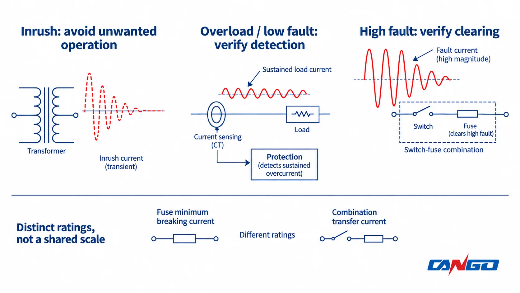
The same transformer capacity can lead to different choices
Consider three comparison conditions without prescribing a fuse size or relay setting:
A repetitive distribution substation: the utility accepts a specified switch-fuse arrangement, the load is defined, and an approved fuse selection demonstrates the required coordination. A switch-fuse feeder can remain on the shortlist when its complete protection scope satisfies that specification.
An industrial substation with sensitive earth-fault requirements: the minimum earth-fault current and required operating time govern detection. A breaker-and-relay feeder may be the appropriate route if its sensing, enabled functions and trip supply provide that coverage. Transformer kVA alone cannot establish this.
An installation with changed loading or downstream protection: replacing an LV main breaker, altering its settings, increasing permitted load or changing the transformer can invalidate the original coordination assumptions. Review both architectures again against the revised data.
These examples are decision conditions, not capacity rules. A manufacturer or utility selection table can define a usable range for a named combination; that range should not become a universal switch-fuse-to-VCB breakpoint.
Prepare a comparable RMU transformer-feeder inquiry
Send both offers the same input package:
- SLD with transformer-feeder and LV protection boundaries.
- System voltage, frequency, maximum fault duty, minimum relevant fault currents and network earthing arrangement.
- Transformer capacity, voltage ratio, vector group, impedance, loading profile, inrush data and thermal/protection accessories.
- Upstream and LV protective-device models, characteristics and the available coordination study.
- Required phase, earth-fault, thermal, external-trip, alarm and remote-control functions.
- Auxiliary-power arrangement, site conditions, utility requirements and required technical documents.
Ask a switch-fuse supplier for the approved fuse reference and combination-coordination evidence. Ask a breaker-and-relay supplier for the sensor, relay, trip and enabled-function schedule. Record who supplies the final protection study, approved settings and commissioning verification.
CANGO’s medium-voltage switchgear and power transformer categories provide the relevant equipment starting points. Use the switchgear quotation checklist and transformer project-information guide to complete the equipment inputs.
For a configuration discussion, send CANGO your transformer-feeder requirements with the SLD and protection requirements. The proposed equipment combination must be confirmed against the project’s engineering and utility specification.