Before requesting a power transformer quotation, gather the information that describes both the electrical supply and the installation. A capacity value is a starting point, but it does not describe the complete equipment requirement.
Record the project’s electrical requirements
Provide the required primary and secondary voltages, frequency, phase arrangement and rated capacity. Include the project specification for connection, tapping and impedance requirements where available. If the load schedule is still being reviewed, say so clearly rather than treating an estimate as an approved rating.
For replacement equipment, include the existing nameplate and explain whether the aim is like-for-like replacement or a change in capacity or system arrangement.
Keep the load assessment distinguishable from the selected transformer rating. A load list describes connected equipment, but the demand expected to operate together may differ from the sum of all nameplates. Ask the project engineer to identify the design demand, expected operating power factor, relevant starting conditions and planned expansion. Do not apply an undocumented diversity factor or a standard spare-capacity percentage simply to obtain a convenient catalog selection.
A calculation can be illustrated without inventing project values. Let the approved active demand be P and the associated power factor be pf. The apparent demand is S = P / pf, with consistent units and the power factor expressed as a ratio. Enter the approved demand and power factor, calculate S, and then review the result against the operating and installation requirements. The calculated apparent demand is a design input; it is not automatically the final transformer rating.
For a project with planned additional loads, repeat the calculation for the approved future operating case rather than adding an arbitrary margin. Record whether the loads are simultaneous and identify conditions such as starting duty or unusual load characteristics that need further review. The project engineer then compares the resulting requirements with available manufacturer ratings and applicable service conditions. This is the calculation sequence, not a recommendation for any unmeasured installation.
| Calculation input | Project value/source | How it is used |
|---|---|---|
| Active demand P | Approved operating-load assessment | Use demand for the operating case, not an unexplained connected-load total. |
| Power factor pf | Applicable demand data or design basis | Use with P in S = P / pf; document the source. |
| Future operating case | Approved changes to simultaneous demand | Review separately rather than assuming a universal spare margin. |
| Final equipment rating | Manufacturer data and project engineering review | Confirm suitability beyond the initial apparent-demand calculation. |
Explain where the transformer will be installed
State whether the proposed location is indoors, outdoors or inside a packaged substation. Provide the available space, access route and known environmental conditions. Ventilation and cooling are important installation considerations; manufacturer instructions and the actual equipment rating must guide the final arrangement. See Schneider Electric’s ambient-temperature guidance for background on why installation conditions matter; its product-specific limits should not be applied automatically to another transformer.
For an indoor installation, provide the room arrangement, ventilation concept, access route and surrounding equipment layout. Identify any limits on bringing the transformer into the room or removing it later. The installation should accommodate the selected equipment and its instructions, including access for inspection and maintenance. A room drawing that shows only the transformer footprint does not demonstrate that handling and cooling interfaces have been coordinated.
For an outdoor installation, describe exposure and the proposed enclosure or protection arrangement required by the project. Record site conditions that may affect selection and identify whether they are measured, specified or still awaiting confirmation. Do not assume that a construction described as outdoor is suitable for every environment or that adding an enclosure has no effect on the thermal arrangement. Confirm the selected model and enclosure together against manufacturer documentation.
If the transformer sits inside a prefabricated substation, review it as part of that package. Identify ventilation openings or environmental-control equipment, adjacent assemblies, cable routes and maintenance access. Allocate responsibility for the complete enclosure arrangement rather than treating the transformer as an isolated item. The checklist below separates installation questions; it deliberately does not prescribe generic clearances, ventilation rates or environmental ratings that may not apply to the selected equipment.
| Location | Information to provide | Confirmation needed |
|---|---|---|
| Indoor room | Layout, access route and ventilation concept | Review cooling and service access for the actual model. |
| Outdoor position | Exposure, site conditions and required protection | Confirm enclosure and equipment compatibility. |
| Packaged installation | Overall enclosure and adjacent-equipment arrangement | Coordinate ventilation, connections and maintenance access. |
| Delivery/replacement | Handling route and known restrictions | Check selected equipment dimensions and handling instructions. |
Identify the equipment interfaces
- Connection to the incoming switchgear and outgoing distribution equipment.
- Proposed cable or busbar connections and termination arrangements.
- Monitoring, protection and auxiliary requirements.
- Handling, placement and access constraints at the site.
Where a transformer is part of a wider equipment package, share the overall single-line diagram. This makes the intended boundaries between the transformer, switchgear and other project equipment easier to discuss.
Locate each electrical and mechanical boundary on the project drawings. For the primary connection, identify the upstream equipment, cable or busbar arrangement and the party supplying termination accessories. Repeat this for the secondary connection and any neutral or earthing interface. A shared voltage designation does not guarantee that cable entries, terminal positions or connecting equipment will fit the proposed installation.
Provide the required monitoring and protection interfaces as a schedule. Distinguish supplied sensors or devices from external wiring, power supplies and integration with site systems. Identify the party responsible for protection settings and related project studies. The quotation should state what equipment and documentation it supplies without implying that the complete installation protection design is included automatically.
Mechanical interfaces deserve the same discipline. Show the proposed support, access and cable route and identify existing dimensions that need site verification. For replacement work, explain whether existing connections will be retained or modified. Request the selected general arrangement before finalizing dependent civil or cable work. Where information remains unavailable, ask the supplier to state the assumption and the affected interface so it can be resolved before manufacturing.
| Interface | Data to exchange | Boundary to agree |
|---|---|---|
| Primary connection | Upstream equipment and termination arrangement | Cables, accessories and external connection work. |
| Secondary/neutral | Receiving distribution and required connections | Busbar/cable interfaces and earthing responsibilities. |
| Monitoring/protection | Specified functions, signals and auxiliary supply | Devices, external wiring, settings and integration. |
| Mechanical | Support, access and selected outline drawing | Civil interfaces and handling/installing responsibilities. |
Compare the complete specification
When reviewing offers, compare the confirmed technical schedule, supplied accessories, required documents and delivery scope. If two offers use different assumptions, resolve those differences before comparing price alone.
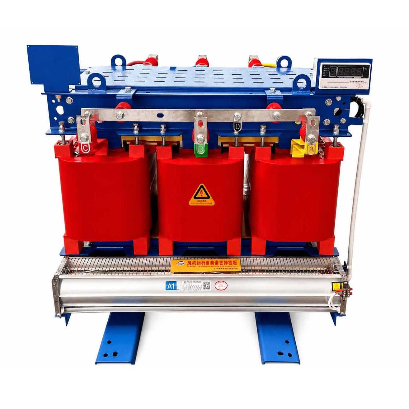
CANGO’s transformer catalog includes oil-immersed and dry-type product families. Discuss the project specification and installation conditions with our team to review the relevant equipment. Final suitability depends on the selected model and the agreed project requirements.
Use a technical comparison sheet that keeps the requirement, offered data and reference conditions together. Compare the same rated capacity, voltage combination and cooling configuration. Otherwise, a lower loss figure or different impedance value may describe different equipment rather than a better offer for the specified duty. Ask suppliers to identify the relevant manufacturer table and any departures from the project schedule.
Loss values need their units, rating and stated reference conditions. Keep no-load and load loss separate and do not compare figures expressed in different units without an explicit, checked conversion. Impedance and connection group should be compared with project requirements, not ranked as generically higher or lower being better. These characteristics interact with the wider installation and require the project design team to confirm their acceptability.
Complete the comparison with tapping requirements, supplied accessories, monitoring, documents and installation assumptions. Identify which values remain subject to configuration review. A technical alternative should have its own schedule and deviation list, so the purchasing decision does not combine attractive features from incompatible configurations. The aim is to establish a like-for-like basis before commercial evaluation, while retaining manufacturer confirmation for all model-specific data.
| Characteristic | What to compare | Avoid this mistake |
|---|---|---|
| Losses | Same rating, units and reference conditions | Comparing isolated numbers from different configurations. |
| Impedance | Project-required value and applicable rating | Assuming an arbitrary increase or decrease is always beneficial. |
| Connection group/tapping | Required system arrangement and offered configuration | Treating a catalog option as an approved project selection. |
| Accessories/documents | Defined supplied scope and deliverables | Assuming all installation functions belong in the equipment offer. |
Prepare your inquiry package
A concise package can include the technical specification, load schedule, site layout, quantity and delivery destination. Add the existing transformer’s details for replacement projects. Tell us which information is confirmed and which items need clarification.
Explore CANGO power transformers or review the industrial power distribution guide.
DISCUSS YOUR TRANSFORMER REQUIREMENTS ↗
Put the approved electrical requirements and open questions in a cover schedule. Attach the load assessment, single-line diagram and site layout, plus any utility or customer specifications that govern the equipment. State the quantity, destination and requested supply boundary. For replacement work, include readable nameplate photographs and explain which existing interfaces are intended to remain.
Use a document register to identify current revisions. Separate a manufacturer reference used for background from the project specification that sets the requirement. If two documents disagree, identify the discrepancy and responsible reviewer rather than expecting the supplier to select whichever value seems convenient. Make provisional information visibly different from confirmed requirements in the inquiry and subsequent clarification record.
Request the response in a format that can be reviewed against the same register: offered technical schedule, outline information, deviations, required documents and exclusions. State what questions must be answered before procurement and what information must be agreed before manufacturing. This helps keep purchasing, design and installation teams aligned without implying that an early quotation settles every engineering interface or project-specific commercial term.
| Inquiry attachment | Why it is needed | Status check |
|---|---|---|
| Electrical schedule/load assessment | Establish required duty and operating cases | Identify approval source and unresolved design questions. |
| Site/interface drawings | Coordinate equipment with the installation | Mark dimensions and interfaces awaiting verification. |
| Existing-equipment record | Explain replacement constraints | Distinguish retained interfaces from proposed changes. |
| Document/clarification register | Keep the current basis traceable | Identify superseded revisions and accepted deviations. |
Turn the nameplate request into a coordinated specification
Organize the inquiry around the transformer and its connections. Provide the required capacity and voltage combination together with the project requirements for connection group, tapping and impedance. If the design team has not confirmed a value, mark it as an open point. Copying a value from a previous project can conceal differences in the network and installation.
For a replacement, send a readable nameplate image, terminal arrangement and existing protection information. Explain whether the load, supply arrangement or operating method will change. The old transformer is useful evidence about the installation, but it does not by itself establish the correct requirements for a changed project.
Compare oil-immersed and dry-type proposals within the installation context. Consider the proposed location, cooling and ventilation arrangements, access and the project specification. Do not select solely from a general claim that one construction is always preferable. The selected model, installation instructions and applicable project requirements must be reviewed together.
Consider an illustrative replacement inquiry that initially contains only a photograph of the existing transformer nameplate. It establishes useful information about the installed unit, but not whether the same selection is appropriate after the building load or supply arrangement changes. The buyer should explain the intended change and attach the updated system and installation information before treating the old data as the new specification.
The coordinated request records which electrical characteristics the project requires, which physical interfaces must remain and which items may be redesigned. It distinguishes the upstream switching arrangement from the transformer itself and identifies the receiving distribution equipment. A change register makes the difference between a like-for-like replacement and a redesign visible. No actual capacity or connection group is prescribed by this example.
Ask the supplier to return a schedule against these requirements, with model-specific data confirmed from manufacturer documents. Review any deviation with the project engineer and reconcile the selected outline with the site arrangement. Keep the accepted technical schedule and drawings together so the equipment ordered, delivered and installed can be traced to the same agreed configuration.
| Initial nameplate inquiry | Coordinated requirement | Decision record |
|---|---|---|
| Existing rating only | Approved present/future operating duty | Explain whether the project duty changes. |
| Existing dimensions only | Verified retained interfaces plus selected outline | Identify physical modifications or unresolved fit. |
| General replacement request | Defined technical and installation supply boundary | Record accepted configuration and deviations. |
Inquiry review checklist
| Review area | Information to provide | Decision to confirm |
|---|---|---|
| Electrical schedule | Capacity, voltage combination, frequency and phases | Separate confirmed values from design questions. |
| System interfaces | Connection group, tapping, impedance and protection requirements | Coordinate with incoming and outgoing equipment. |
| Installation | Location, available space, ventilation and access | Review the actual model and general arrangement. |
| Offer review | Accessories, losses at stated conditions, documents and supply boundary | Compare like-for-like information, not isolated figures. |
Where suppliers quote losses or other performance data, ask for the rating and reference conditions associated with those values. Do not compare an isolated number from one rating with a figure for another configuration. Record the documents required for review and the responsibility for installation and commissioning. A clear handover package should allow the project team to trace the supplied equipment back to the agreed technical schedule.
Related reading
- How to Size a Distribution Transformer in kVA
- Oil-Immersed vs Dry-Type Transformers: How Project Buyers Should Compare Them
FAQ
Can a transformer be specified by kVA alone?
No. Provide the voltage combination, frequency, phase arrangement and the project requirements for connection, tapping and impedance, together with installation information.
What should I send for a replacement transformer?
Send the existing nameplate, drawings, connection details and installation constraints. Explain whether the project is a like-for-like replacement or includes a change in capacity or system arrangement.
Should I choose oil-immersed or dry-type equipment first?
Review the installation and project requirements with the available equipment families. Location, cooling, access and the selected model matter; construction type alone does not establish suitability.
How should transformer losses be compared?
Compare figures for the stated rating and reference conditions. Ask the supplier to identify those conditions so figures for different equipment configurations are not treated as equivalent.
Which documents belong in the inquiry package?
Include the technical specification, load schedule where available, site layout, quantity and destination. Add existing equipment details for replacement work and mark information that still needs confirmation.
References
- CANGO Power, Power Transformers Portfolio (CANGO product category information).