A low-voltage switchgear inquiry needs more than an incoming current rating. To define a useful proposal, the supplier needs to understand the supply arrangement, outgoing loads, fault conditions and the space in which the assembly will operate. A short, coordinated information package helps avoid quotations based on different assumptions.
Start with the single-line diagram
The single-line diagram should identify incoming sources, bus sections, any bus coupler and the outgoing feeders. Where a generator or a second transformer is involved, state the intended operating arrangement. Do not leave the supplier to assume whether sources operate separately or in parallel.
Attach the load schedule and identify which circuits are motors, general distribution or other loads. Mark future feeders separately from circuits required at first installation. This makes it easier to distinguish spare physical space from capacity that must be available from day one.
Turn project information into equipment requirements
| Information to provide | What it helps establish |
|---|---|
| System voltage, frequency and earthing arrangement | The electrical context for the assembly and connected devices. |
| Incoming sources and feeder schedule | The number and arrangement of incoming, coupling and outgoing circuits. |
| Available short-circuit data at the installation point | The fault-duty requirements to be reviewed for the assembly and protective devices. |
| Ambient conditions and installation location | Enclosure, ventilation and service-condition requirements. |
| Cable entry, room dimensions and access route | Physical layout, termination space and delivery sections. |
| Maintenance and expansion needs | Access arrangements, spare ways and the appropriate equipment configuration. |
Check the room as carefully as the electrical schedule
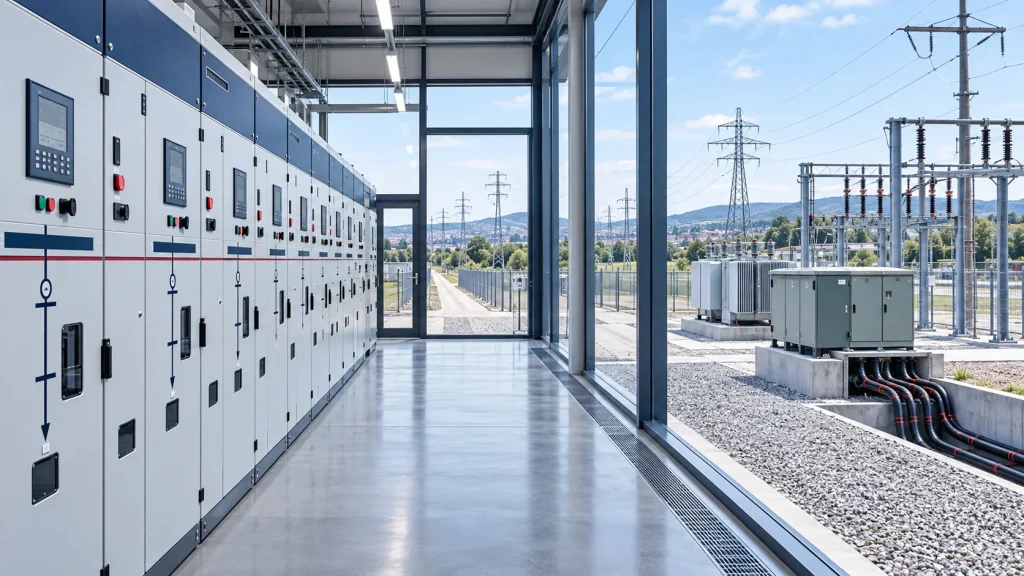
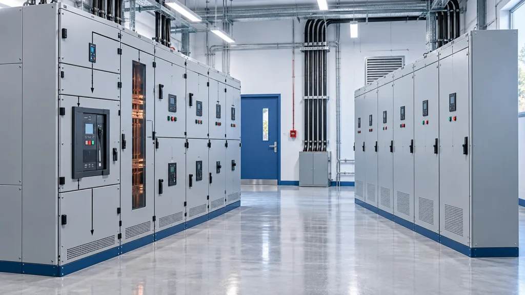
A cabinet that fits the floor plan may still leave too little room for cable termination, opening doors or maintenance. Provide the available room dimensions, access doors, cable trench position and any restrictions on front or rear access. State whether delivery involves stairs, lifting restrictions or narrow corridors.
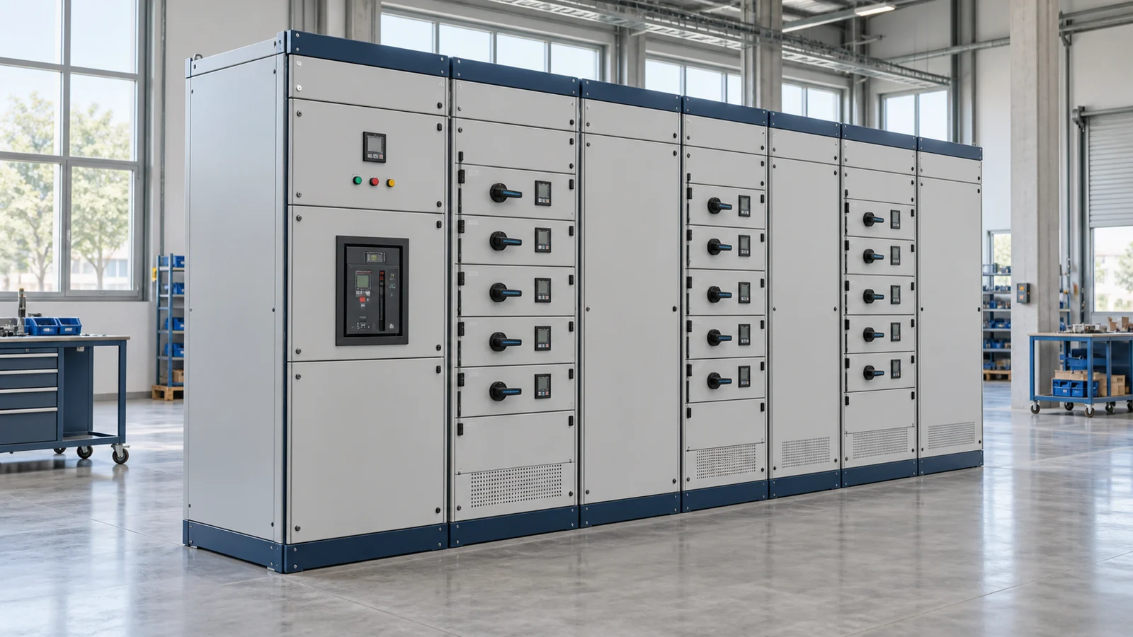
For low-voltage switchgear, the final arrangement should be agreed through the general arrangement drawing and project specifications. Photographs of an existing board can help explain the site, but they do not replace electrical and dimensional data.
Ask for assembly-level documentation
IEC 61439-1 sets general requirements for low-voltage switchgear and controlgear assemblies, including service conditions and verification. A list of branded components is not a substitute for reviewing the completed assembly’s applicable requirements. Specify the required documentation and confirm its scope against the proposed configuration.
Before comparing offers, check that each uses the same drawing revision, circuit schedule, installation assumptions and supply boundaries. Record unresolved items explicitly so that a preliminary quotation is not mistaken for an approved manufacturing design.
Technical reference: IEC 61439-1:2020 — general rules for low-voltage assemblies.