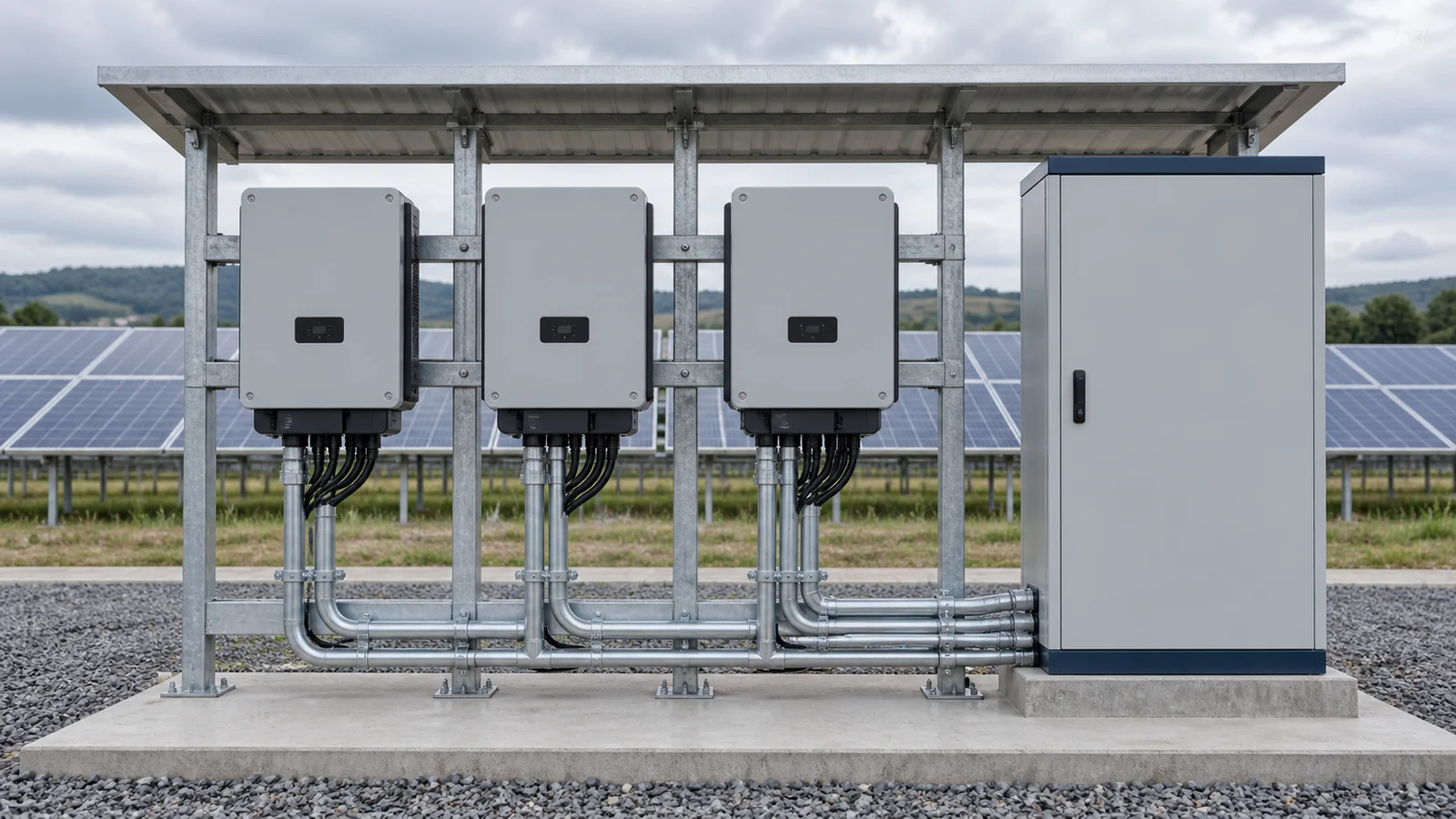
A photovoltaic grid-connection cabinet is part of the electrical path between the inverter output and the site’s connection point. Its scope depends on the installation: it may collect several inverter circuits, provide switching and protection, or incorporate specified metering and interface functions. It does not replace the inverter, and one cabinet layout cannot suit every utility connection.
Separate the DC side from the AC side
Solar modules produce direct current (DC). The inverter converts this to alternating current (AC) for connection to the electrical installation. Equipment selected for the inverter’s AC output must be assessed for that AC system; a DC combiner box and an AC collection cabinet serve different positions in the circuit.
The inverter documentation is an important starting point because it defines the output characteristics and the manufacturer’s connection requirements. The project design then needs to coordinate these with the receiving switchboard and the network connection conditions.
Draw the electrical boundary at the inverter before preparing the cabinet inquiry. On the DC side, information about module strings, DC collection and inverter input belongs to a different part of the installation from the inverter AC output and receiving distribution system. A device described as a combiner box should not be selected solely because its name sounds similar to an AC collection cabinet. State the position and function on the project single-line diagram.
For the AC cabinet, request the inverter output data and the actual arrangement of inverter feeders. Identify whether the cabinet collects multiple outputs, provides specified switching and protection, or performs another defined AC distribution role. A diagram should show where the inverter output terminates and where the next equipment connection begins. If a transformer is involved, include that interface rather than treating it as a separate unexplained item.
The boundary schedule should allocate documentation as well as equipment. Identify who provides inverter instructions, project protection requirements and utility connection conditions. A cabinet supplier may need these documents to review the requested assembly without being responsible for designing the entire solar installation. Mark which requirements come from the inverter manufacturer and which come from the network or project design.
Use the following worksheet to keep the two sides distinguishable. It does not prescribe a complete solar-system architecture or assert that any particular item is included in the cabinet supply. The actual installation may use a different collection arrangement, so equipment selection and supply responsibilities must follow the approved project design and the selected manufacturer documentation.
| Circuit position | Relevant information | Boundary to state |
|---|---|---|
| PV/DC collection | Module/string arrangement and inverter-input requirements | Identify separately supplied DC-side equipment. |
| Inverter | Model, instructions and AC output data | Identify conversion equipment and its specified interfaces. |
| AC collection cabinet | AC feeder arrangement and requested assembly functions | Define included switching, protection and termination scope. |
| Receiving system | Distribution/transformer connection and grid requirements | Allocate external equipment, cables and approval responsibilities. |
Define the interfaces before selecting a cabinet
| Interface | Information to agree | Scope question |
|---|---|---|
| Inverter to AC collection | Inverter quantity, model, output ratings and feeder arrangement. | Which outgoing inverter cables and termination accessories are included? |
| AC collection to site distribution | Connection voltage, cable route and receiving-board details. | Who supplies the interconnecting cables and any modifications to the existing board? |
| Site to utility | Approved connection requirements and metering arrangement. | Which protection, metering and disconnection functions belong inside the cabinet? |
| Controls and monitoring | Required signals, communications and export-control responsibilities. | Who integrates and commissions the interface? |
Create an interface entry for every connection crossing the cabinet boundary. For an inverter feeder, identify the inverter reference, electrical output information, cable entry and required termination arrangement. For the outgoing connection, identify the receiving equipment and the party supplying the interconnecting cable or busbar. Keep physical connection information alongside electrical duties, because a compatible voltage alone does not establish that the interfaces are coordinated.
Controls and monitoring need a similar schedule. Describe the signals or communications required, their purpose and the receiving system. Identify whether they concern indication, measurements, commands or an export-control function. State the party responsible for external wiring, system configuration and integration testing. Avoid using a general phrase such as monitoring included when the actual required interface has not been defined.
For a retrofit, provide existing switchboard drawings, available connection details and the installation constraints affecting the proposed cabinet. Mark information that requires a survey or further engineering review. If the project requires changes to existing protection or metering, identify those changes explicitly. A new cabinet offer should not be interpreted as including modifications to every connected system unless that scope is stated.
The example below is a responsibility worksheet rather than a fixed division of work. Ask each relevant supplier or project party to confirm its part and record open items. Before manufacturing, reconcile the interface schedule with the single-line diagram and cabinet drawings. This creates a clear record of what the assembly supplier is delivering and what must be coordinated elsewhere.
| Interface entry | Information attached | Responsibility to confirm |
|---|---|---|
| Inverter feeder | Inverter reference, output data and cable arrangement | Inverter supplier, AC assembly supplier and cable installer boundaries. |
| Outgoing feeder | Receiving equipment reference and connection details | Interconnecting cable/busbar and receiving-board work. |
| Monitoring/control | Signal purpose and required communications | External wiring, configuration and integration testing. |
| Existing installation | Current drawings and proposed modifications | Survey, design review and site-work responsibilities. |
Use the connection point to frame the review
The connection point affects how the existing installation and solar production interact. Provide a single-line diagram showing the inverter feeders, the proposed AC cabinet, existing loads and the point of connection. If export limitation is required, identify the specified control system and its measurement location rather than assuming the cabinet alone provides that function.
Protection and switching must be coordinated with the system design, inverter instructions and applicable network requirements. Avoid selecting equipment solely from the solar array’s nameplate power: the AC output data and the actual installation conditions also matter.
The connection point gives the project team a common reference for how solar generation interacts with the existing supply and loads. Show it clearly on the single-line diagram and identify the equipment on both sides. State whether the project connection conditions include export restrictions, particular metering or protection requirements, and identify the document that establishes them. Do not infer the approved arrangement from a generic grid-connection cabinet diagram.
Where export limitation is required, identify the measurement location, specified control system and the party responsible for its integration with the inverters and installation. A switching cabinet does not automatically perform every control function needed at the connection point. Ask the offer to identify included devices and signals and to state any assumptions about equipment supplied by other parties.
Protection and disconnection arrangements should be reviewed against inverter instructions, the receiving system and applicable connection requirements. State who performs the necessary design and coordination work and who obtains project or utility approval. The equipment quotation may provide important technical information for that process without being approval of the complete solar installation. Keep that distinction visible in the inquiry and accepted scope.
Use an unresolved-item list for information not yet issued by the utility or project engineer. Record what the supplier may assume at quotation stage and what must be confirmed before manufacturing or connection. If the connection point changes, revisit the affected metering, control and cable interfaces instead of changing only a label on the drawing.
| Connection-point check | Evidence to obtain | Question to close |
|---|---|---|
| Location and circuit arrangement | Current project single-line diagram | Where exactly does the PV installation connect? |
| Utility/customer conditions | Applicable issued connection requirements | Which functions and approvals are mandatory for this project? |
| Export control | Specified controller and measurement arrangement | Who integrates and verifies the complete function? |
| Protection/metering | Relevant schedules and design responsibility | What is inside the cabinet and what remains external? |
Prepare a clear supply boundary
For photovoltaic grid-connection equipment, send the inverter datasheets, drawing revision, site conditions and the required cabinet scope together. Include outdoor exposure, cable entry and access constraints where relevant.
A useful proposal states what the assembly includes, what other parties provide and what remains subject to utility or engineering approval. This keeps an equipment quotation separate from the approval of the complete solar installation.
Technical references: Schneider Electric’s Electrical Installation Guide on integrating solar production and inverter conversion and power quality.
Prepare an inclusion schedule covering the assembly, internal equipment, connecting accessories, documentation and services. Ask for the exact offered scope and keep alternative configurations separate. A cabinet shown in a catalog establishes a product family, not a complete contract for every solar installation. The quotation should identify the proposed arrangement against the project documents and explain deviations or information still needed.
Distinguish equipment delivery from site work. Identify external cables, receiving-board modifications, earthing connections and installation activities that other parties must provide. State which commissioning and integration activities are requested from the cabinet supplier and which are arranged separately. Do not assume that a necessary project activity is included simply because the cabinet cannot operate without it.
For outdoor or constrained installations, show the proposed position, exposure and access requirements. Include cable entry and termination restrictions and ask for confirmation of the selected enclosure and arrangement. Manufacturer data must confirm any model-specific rating, environmental limitation or physical requirement. Do not substitute dimensions or service conditions from a different cabinet for the actual offered configuration.
The accepted boundary should be consistent across purchasing and engineering documents. If the cabinet schedule includes metering but the scope excludes the associated external measurement or communications work, explain the interface explicitly. Keep open questions in the clarification register until the responsible party confirms them. This avoids discovering a gap only when the site installation is ready for connection.
| Scope area | Ask the offer to identify | Allocate outside the offer |
|---|---|---|
| Cabinet assembly | Included functional equipment and accessories | Separately supplied inverters and receiving equipment. |
| Connections | Internal and boundary termination arrangements | External cables, supports and site connection work. |
| Controls/documents | Included interfaces, drawings and records | Project studies, external configuration and approvals. |
| Installation/services | Any specifically included site activities | Installation, commissioning and integration responsibilities. |
Use an interface schedule to define the AC cabinet scope
Start from the inverter AC output and trace the connection to the receiving distribution equipment. Mark the quantity and arrangement of inverter feeders, collection points and the grid connection point on the single-line diagram. Use inverter output information for the AC equipment review rather than treating solar module DC nameplate power as a complete cabinet specification.
Prepare a responsibility schedule for switching, protection, metering and monitoring. If export limitation or another network interface is required, identify the measurement location, specified controller and integration responsibility. A cabinet containing switching devices does not automatically provide every function needed for an approved connection.
For an existing facility, provide the receiving-board details and describe the work required outside the new cabinet. Identify who reviews spare ways, cable terminations and changes to protection or metering. Keep equipment supply, utility approval and installation responsibilities distinct so a cabinet quotation is not taken as approval of the whole solar system.
Consider an illustrative project with inverter feeders connecting through an AC cabinet to existing site distribution. At first, the buyer knows the intended connection area but has not issued the final inverter output schedule or utility interface requirements. An early offer can be discussed against provisional assumptions, but it should not be treated as a final cabinet design or confirmation that the receiving board needs no modification.
A coordinated inquiry adds the inverter datasheets, feeder references, receiving-board information and the applicable connection requirements. Each interface has a named responsibility: inverter output documentation, cabinet configuration, interconnecting cables, site controls and approvals. The schedule then shows how the equipment fits into the project instead of relying on a broad statement that the cabinet is grid ready. No actual electrical rating or site approval is implied by this example.
Before finalizing the offer, compare the scope schedule with the drawing and verify that the same interfaces are described in both. If an item changes, identify the affected equipment, signals and documents. The accepted record should make clear which configuration is offered and which work remains with other parties. Model-specific data and installation instructions remain subject to manufacturer confirmation.
This approach is particularly useful when multiple organizations provide different parts of the system. It lets the buyer compare offers on the same basis while giving each specialist a clear interface to review. It also prevents the cabinet supplier from being assumed to guarantee functions that depend on external controllers, inverter settings or utility decisions not included in the equipment scope.
| Schedule field | Example entry to complete | Review result |
|---|---|---|
| Equipment references | Project inverter, cabinet and receiving-board identifiers | Use the same identifiers in drawings and quotations. |
| Technical basis | Datasheets and issued connection requirements | Identify missing or provisional information. |
| Responsibility | Supply, external wiring, configuration and approval owner | Close gaps and overlaps between parties. |
| Revision/status | Current documents and accepted clarifications | Separate indicative discussion from a confirmed equipment offer. |
Inquiry review checklist
| Review area | Information to provide | Decision to confirm |
|---|---|---|
| Inverter output | Inverter datasheets and AC feeder schedule | Define the equipment at the inverter-to-cabinet interface. |
| Receiving installation | Connection point, receiving-board details and cable route | Identify work outside the cabinet supply. |
| Grid interface | Applicable connection, protection and metering requirements | Allocate approval and integration responsibilities. |
| Site constraints | Exposure, enclosure location, cable entry and access | Review installation conditions for the proposed assembly. |
Before accepting the offer, reconcile the electrical drawing with the cabinet schedule and the stated exclusions. Confirm included termination accessories, signals and document requirements. Record outstanding utility or engineering decisions explicitly. Final cable selection, protection coordination and installation approval belong to the complete project design and should not be inferred from a standard cabinet description.
Related reading
- IEC 61439 Design Verification vs Routine Verification for Low-Voltage Switchgear
- LV Switchgear Busbar Sizing and Short-Circuit Withstand
FAQ
Is an AC grid-connection cabinet the same as a DC combiner box?
No. They serve different positions in the circuit. Use the inverter AC output information and the receiving-system requirements when specifying AC collection and connection equipment.
Can I select the cabinet only from the PV array power?
No. Provide inverter AC output data, feeder arrangements and the connection-point requirements. The module nameplate power does not describe every AC interface.
Does the cabinet automatically provide export limitation?
Do not assume so. Identify the specified control system, measurement location and responsibility for integration when export limitation is required.
Who handles utility connection approval?
Allocate this responsibility in the project scope. A cabinet proposal should identify its equipment boundaries and outstanding approvals rather than imply approval of the complete installation.
What should be included with the inquiry?
Send inverter datasheets, the current single-line diagram, site conditions, receiving-board details and the required protection, metering and monitoring scope. Identify work provided by other parties.
References
- International Electrotechnical Commission (IEC), IEC 61439 series: Low-voltage switchgear and controlgear assemblies (standard scope referenced).
- CANGO Power, Solar PV Grid Connection Equipment (CANGO product category information).