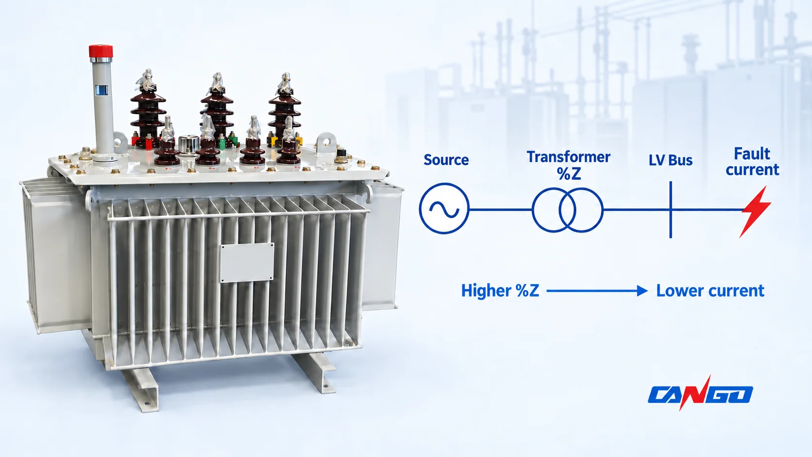
At the same transformer kVA and secondary voltage, a lower percent impedance permits a higher short-circuit current. For one transformer supplied by an ideal strong upstream source, a first estimate is rated secondary current divided by impedance in per unit. A 1 MVA, 400 V transformer with 6% impedance gives approximately 24.1 kA symmetrical RMS for a three-phase bolted fault at its LV terminals, using a consistent 400 V base and voltage factor c = 1.
That number explains the effect of %Z. It does not establish the final fault duty of the installed LV board. Source strength, the connection between transformer and board, operating configuration and the study assumptions must also be known.
What transformer percent impedance means
Transformer percent impedance expresses a short-circuit impedance voltage relative to rated voltage. In the test principle, one winding is short-circuited and a reduced voltage on the other produces rated current. Expressing that voltage as a percentage of the corresponding winding’s rated voltage gives %Z. The BC transformer learning guide, learning task 7 explains this relationship.
%Z = short-circuit test voltage / corresponding rated voltage × 100
A 6% value therefore means 0.06 per unit on the transformer’s stated rating and voltage bases. It does not mean the transformer loses 6% of its power.
The underlying series impedance has resistance and leakage-reactance components: Z = R + jX. Its magnitude combines both. Schneider Electric’s short-circuit impedance definition specifies rated frequency, reference temperature and a particular tapping. Those conditions matter when comparing a specification, nameplate and test result.
The resistive component is associated with losses; the reactive component is associated with leakage flux rather than perfect magnetic coupling between windings. A nameplate %Z gives the impedance magnitude, not a complete R/X model. It is also not automatically the percentage reduction in secondary voltage at a particular load power factor.
The short-circuit estimate from %Z
For a three-phase transformer, first calculate rated secondary line current:
IFL = S / (√3 × VLL)
Use S in VA and line-to-line secondary voltage VLL in volts to obtain amperes. If S is in kVA, multiply it by 1,000.
The ideal strong-source terminal estimate is then:
Ik,estimate = IFL / zT = IFL × 100 / %Z
Here zT is transformer impedance in per unit. Divide by 0.06, or multiply by 100/6, for a 6% transformer. Dividing current directly by 6 would produce a result 100 times too small.
Schneider Electric’s secondary-terminal calculation guide uses this simplified relation when upstream MV-system impedance is negligible. The calculation below assumes one transformer, an ideal strong source, a three-phase zero-impedance fault at its LV terminals, and c = 1. It ignores source and connection impedance, other fault-current contributions and study corrections. The result estimates the initial symmetrical AC component in RMS amperes; it is not the instantaneous peak.
Worked example: 1 MVA, 400 V, 4% versus 6% versus 8%
Hold rated power and voltage constant so that only impedance changes:
IFL = 1,000,000 / (√3 × 400) = 1,443.4 A
For 6% impedance:
Ik,estimate = 1,443.4 / 0.06 = 24,056 A ≈ 24.1 kA
| Transformer impedance | Per-unit value | Full-load line current | Estimated terminal fault current |
|---|---|---|---|
| 4% | 0.04 | 1,443.4 A | 36.1 kA RMS |
| 6% | 0.06 | 1,443.4 A | 24.1 kA RMS |
| 8% | 0.08 | 1,443.4 A | 18.0 kA RMS |
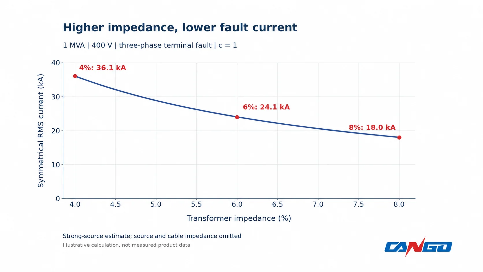
Changing from 6% to 4% raises this estimate by 50%, although the transformer has exactly the same kVA rating. Changing from 4% to 8% halves it. These are comparison values, not a claim that every transformer family offers all three impedances.
The voltage basis must remain consistent. A rated-current calculation at 400 V should not be combined casually with a guide table based on 420 V no-load voltage. For the final study, use the selected transformer’s actual rating, tap data and the voltage assumptions required by the calculation method.
Why the installed system can give a different result
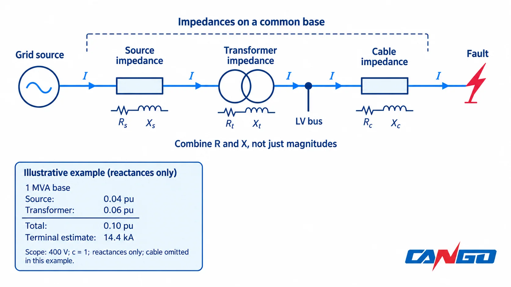
The fault sees the equivalent network impedance upstream of its location. For a terminal fault that includes the source and transformer. For a fault beyond a cable, the cable adds impedance. Schneider Electric’s LV fault-current method combines series resistances and reactances separately before finding the total impedance magnitude.
A finite upstream source changes the terminal estimate
Assume the same 1 MVA, 400 V, 6% transformer, but give the upstream network an illustrative three-phase short-circuit power of 25 MVA. Refer all quantities to a common 1 MVA base with compatible voltage bases across the transformer. For this example only, treat both source and transformer impedance as purely reactive and retain c = 1:
xQ ≈ Sbase / Ssc,Q = 1 / 25 = 0.04 pu
xtotal ≈ 0.04 + 0.06 = 0.10 pu
Ik,estimate ≈ 1,443.4 / 0.10 = 14.4 kA RMS
The ideal strong-source result was 24.1 kA. Adding this finite-source impedance reduces the estimate substantially. The addition of 0.04 and 0.06 is valid here because the example explicitly treats both as reactances on the same base. In a general calculation, add complex impedances or their R and X components; do not simply add two impedance magnitudes or percentages taken from different equipment bases.
This extra calculation still does not constitute a completed IEC 60909-0:2026 study. Relevant voltage factors, transformer corrections, impedance tolerance, taps and operating states remain to be applied. The strong-source shortcut is not a guaranteed maximum: some of these omitted factors can raise the calculated duty.
RMS fault current does not give peak current
Fault current can contain a decaying DC offset. The network X/R ratio affects its decay and the first peak, so two systems with the same symmetrical RMS current can impose different peak duties. ABB’s short-circuit handbook, section 6.6 explains the relationship between R/X, initial RMS current and peak current.
For an installation study, also identify motors, generators, parallel transformers and converter-based sources that can contribute, together with permitted bus-coupler and source operating states. Maximum duty and minimum current for reliable protection operation are separate cases. An earth fault additionally needs the earthing arrangement and relevant sequence impedances; positive-sequence transformer %Z alone is insufficient.
Translate fault results into the correct LV equipment duties
A statement such as “24 kA switchgear” leaves the quantity and conditions unclear. The assembly and its circuit breakers have different duties:
| Quantity | Applies to | What the review must establish |
|---|---|---|
| Icw, rated short-time withstand current | LV assembly and relevant components | RMS withstand duty for a specified duration, consistent with the protective-device clearing or intentional delay |
| Ipk, rated peak withstand current | LV assembly | Ability to withstand the required peak electrodynamic duty |
| Icu, rated ultimate short-circuit breaking capacity | Industrial circuit breaker | Breaking capability at the actual operating voltage and applicable conditions |
| Ics, rated service short-circuit breaking capacity | Industrial circuit breaker | Breaking duty with specified post-test service-performance checks, including continued rated-current carrying under standardized conditions |
ABB’s assembly guide distinguishes Icw from Ipk; Schneider Electric explains breaker Icu and Ics. A breaker’s Icu does not by itself establish the completed assembly’s withstand capability. Equally, an assembly’s Icw is not its incoming breaker’s breaking capacity.
For Ics, the prescribed short-circuit test sequence is followed by checks of continued service capability, as explained in Schneider’s service breaking-capacity guidance. These standardized test requirements are not a guarantee of immediate reuse after an actual installation fault. Follow the exact breaker manufacturer’s post-fault inspection and return-to-service instructions.
Ask for the proposed configuration’s rated-duty and verification basis. Where current-limiting protection or a conditional assembly rating is used, confirm the specified protective device and its coordination evidence rather than assuming that any breaker with a high kA label qualifies the board.
Lower impedance also changes voltage performance
Choosing %Z is a system tradeoff. For comparable rating and load conditions, lower transformer impedance generally reduces the transformer’s contribution to voltage drop while permitting more fault current. Higher impedance limits the terminal fault contribution but can increase voltage-drop or motor-starting concerns. Schneider Electric’s transformer technical bulletin, glossary pages 15–16 relates impedance to both fault current and voltage drop.
Actual voltage regulation depends on load current, power factor and the separate R and X values. Motor starting adds a transient load case; Schneider Electric’s motor-transformer guidance identifies transformer impedance and starting current as relevant inputs. A 6% impedance label is therefore not a promise of exactly 6% operating voltage drop, nor does the smallest %Z automatically give the lowest losses or the best project choice.
Carry the impedance basis into the transformer specification
Record the following alongside the selected transformer rating:
- Required impedance, tolerance and the tap/reference conditions to which it applies.
- Confirmed transformer R/X or loss data needed to obtain the impedance components.
- Upstream maximum and minimum source fault data, plus the relevant operating configurations.
- Transformer-to-board connection and downstream feeder impedances, with defined fault locations.
- Required symmetrical RMS, peak and time-dependent duties for the LV assembly and protective devices.
Use the agreed IEC 60076-1 transformer framework and the project’s short-circuit calculation basis when confirming the supplied data. If the next step is equipment selection, explore CANGO’s power transformer range with that impedance basis already defined. This allows the transformer and downstream distribution equipment to be reviewed against the same system assumptions.