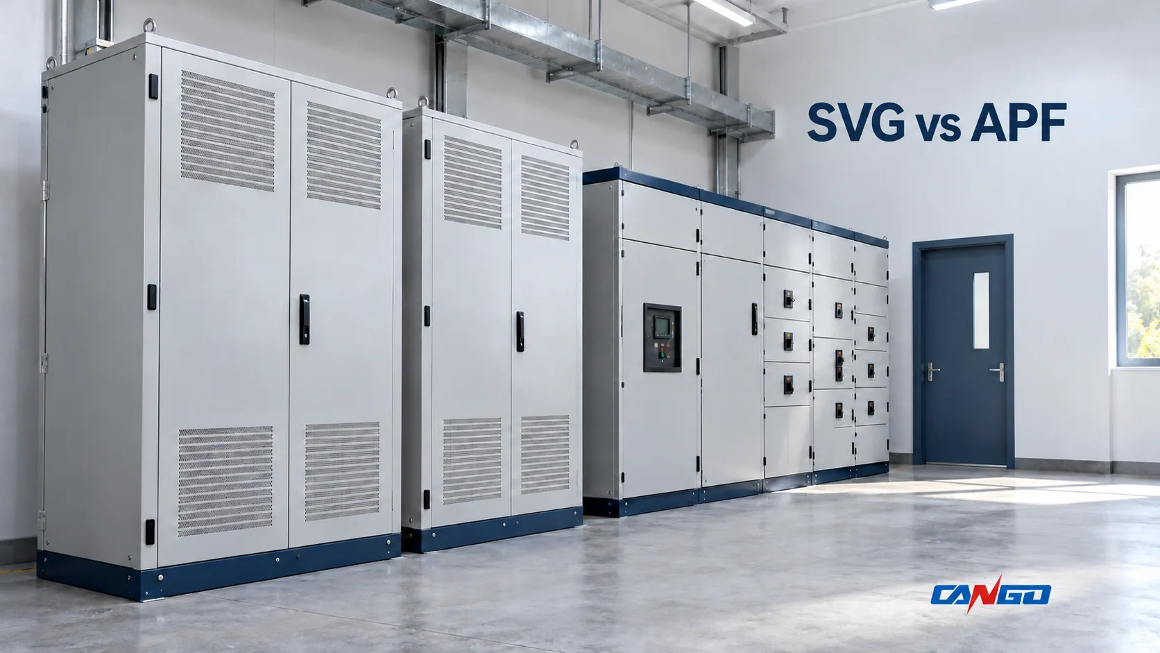
An SVG, or static var generator, primarily compensates fundamental reactive current. An APF, or active power filter—also called an active harmonic filter, AHF—primarily compensates harmonic current. Their functions can overlap: some configurations also address reactive power or load imbalance. The practical choice is therefore the measured duty and available simultaneous compensation capacity, not the abbreviation on the cabinet.
For a low-voltage industrial system, begin by separating poor displacement power factor from current distortion. A motor-heavy installation and a drive-heavy installation may report similar overall power factors but require different compensation priorities.
SVG vs APF: compare the duty, not just the hardware
| Selection question | SVG / electronic var compensation | APF / active harmonic filtering |
|---|---|---|
| Primary compensation duty | Fundamental reactive current, leading or lagging | Harmonic current components selected by the controller |
| Main measurement | Fundamental reactive demand and displacement power factor | Harmonic spectrum, harmonic amperes and the required residual distortion |
| Common nameplate basis | kVAr at a stated system voltage | Compensation current in amperes |
| Possible additional functions | Load balancing or harmonic compensation on specified configurations | Reactive compensation and load balancing on specified configurations |
| Key capacity question | Can it follow the required reactive-current range? | Is enough current available for the simultaneous harmonic and other enabled duties? |
| Do not assume | Every SVG includes a full harmonic-filter function | Every APF can deliver its full harmonic rating and full reactive duty together |
The overlap is real, but model-specific. SVG-type equipment may also be described as electronic var compensation (EVC). For example, TDK documents SVG configurations with load balancing and combinations incorporating active harmonic filtering. An equipment schedule must identify the enabled functions and their ratings rather than infer them from “SVG” or “APF.”
How the compensation currents differ
Both devices can use a controlled voltage-source inverter connected in parallel with the distribution system through coupling inductance. The DC link supports converter operation; the device is not a source of sustained real energy for the load. Semiconductor type, topology, sensing and protection depend on the design, so similar cabinet appearances do not establish interchangeability.
An SVG controls the fundamental current component in quadrature with the supply voltage, supplying or absorbing the reactive current needed for its target. This is more useful for selection than treating it simply as a voltage-amplitude switch. A manufacturer example of the parallel converter and reactor arrangement appears in ACTION’s LV SVG operating description.
An APF measures the electrical quantities required by its control scheme and injects compensating current to reduce the targeted harmonic current flowing upstream. In multifunction operation it can also provide fundamental reactive compensation. Eaton describes both harmonic mitigation and power-factor support in its active harmonic filter overview.
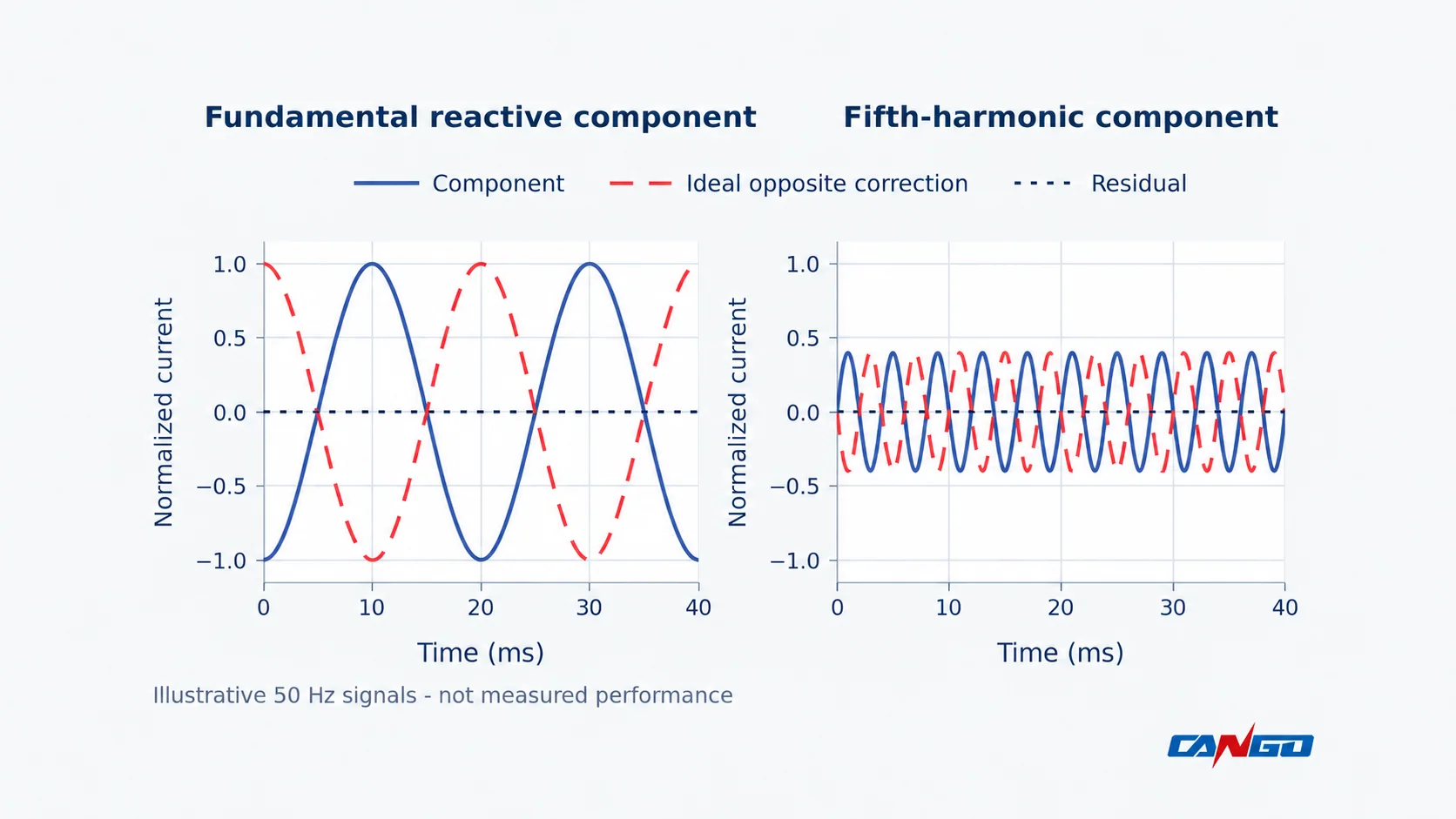
The harmonic range, residual distortion and dynamic response must come from the selected configuration and operating conditions. Neither “all APFs filter orders 2–50” nor “an SVG cannot mitigate harmonics” is a reliable universal specification.
Why displacement power factor is not true power factor
Displacement power factor (DPF) describes the fundamental voltage/current phase relationship. True power factor also reflects waveform distortion. Schneider Electric explains the distinction between displacement and distortion contributions.
Consider an idealized, balanced system with sinusoidal voltage. Normalize its original fundamental RMS current, I1, to 1. Let DPF be 0.80 and the combined RMS harmonic current, Ih, be 0.40. Then:
- Original THDi = Ih / I1 = 40%.
- Original true PF = 0.80 / √(1 + 0.40²) ≈ 0.743.
- The active fundamental component is 0.80; the reactive component is √(1 − 0.80²) = 0.60.
If ideal reactive-only compensation removes that 0.60 component while absolute harmonic current remains unchanged, the new fundamental current is 0.80. DPF becomes 1, but:
- New THDi = 0.40 / 0.80 = 50%.
- New true PF = 0.80 / √(0.80² + 0.40²) ≈ 0.894.
True PF improves, yet distortion remains. The higher THDi here reflects a smaller fundamental-current denominator, not increased harmonic amperes. This calculation is a teaching example, not a predicted site result; distorted voltage and unbalanced operation require a fuller assessment.
Capacity: kVAr, amperes and shared current headroom
For balanced three-phase fundamental reactive compensation, the current corresponding to a stated reactive duty is:
Iq = Q / (√3 × VLL)
Use Q in var and line-to-line voltage VLL in volts to obtain amperes. A kVAr rating cannot be compared with an APF ampere rating without the voltage and duty basis.
For an initial screen with independent, orthogonal reactive and harmonic components, combined RMS compensation current is approximately √(Iq² + Ih²). This excludes balancing duty and practical limits such as per-phase loading, peak current, thermal derating and voltage capability. It is not a final sizing method.
Enabled functions share converter capacity. Schneider’s AccuSine PCS+ dual-mode guidance explicitly describes total-current limits and priority settings when demand exceeds the unit rating. Obtain the equivalent allocation rules for the proposed equipment: a harmonic-priority mode may leave less reactive capacity, while reactive priority may leave more residual harmonics. Ask for simultaneous performance, not separate best-case ratings.
A measured-duty selection matrix
| Measured condition | Architecture to shortlist | What must still be checked |
|---|---|---|
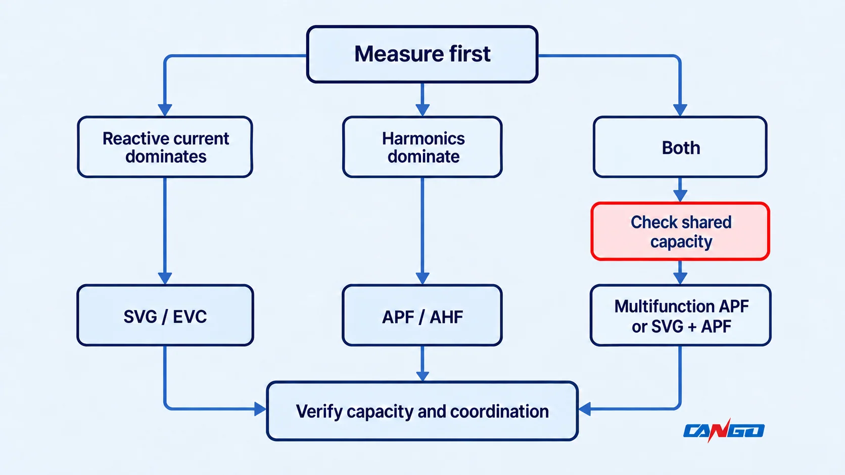
| Reactive demand dominates; harmonic duty is modest against the project target | SVG or electronic var compensation | Leading/lagging range, load variation and actual residual harmonic duty |
| Harmonic amperes dominate; DPF is already acceptable | APF / AHF | Spectrum, per-phase and neutral requirements, operating voltage and residual targets |
| Both duties are substantial | Multifunction APF, or coordinated SVG + APF | Simultaneous current budget, priority behavior and interaction between controllers |
| Existing capacitor stages cover steady reactive demand, but load changes or distortion remain | Coordinated compensation using the existing bank where suitable | Resonance study, stage behavior and sensing/control boundaries |
| Voltage complaints or equipment heating have no confirmed cause | Diagnose before selecting either device | Upstream voltage, loading, connections, imbalance and harmonic evidence |
A combination is not automatically the best solution. It may separate large duties effectively, but adds equipment and coordination requirements. One sufficiently rated multifunction device may meet the duty; conversely, a single device with overlapping features may lack the required headroom.
Reactive support can influence local voltage through network impedance, but neither device name guarantees correction of upstream overvoltage, undervoltage or every flicker problem. Similarly, reducing local harmonic current does not guarantee a specified voltage-distortion result when background distortion is significant.
Agree the acceptance boundary and capacitor coordination
Keep the metrics distinct: THDv describes voltage distortion; THDi references harmonic current to the fundamental current; TDD references harmonic current to a specified maximum-demand current. Meter configuration and the agreed demand basis matter. Schneider’s power-quality measurement guide explains the TDD denominator.
IEEE 519-2022 defines its harmonic-control scope at the point of common coupling, not as a universal device-terminal THDi limit. Record the applicable standard, measurement location, voltage level, operating states and evaluation method. Do not substitute a generic “THDi ≤ 5%” promise for the project requirements.
For projects using Chinese standards, the official national standards listing identifies GB/T 14549-1993 as current and recommended. Its applicability and contractual requirements still need to be established for the project; do not present one percentage as a universal international acceptance rule.
An existing capacitor bank is part of the system design, not an isolated accessory. Capacitors interact with network inductance and can amplify existing harmonics near resonance. Eaton’s capacitor application guidance discusses this interaction. Review the bank ratings, reactors, switching logic and the proposed active device together. CT locations and controller targets must define which currents each device is intended to compensate.
Project inputs for configuration review
Prepare a measurement-backed inquiry with:
- System voltage, frequency, three-wire/four-wire arrangement and single-line diagram.
- Transformer capacity and impedance, plus available source/fault-level information.
- Representative operating profiles: active power, fundamental reactive demand, DPF and true PF.
- Per-phase harmonic spectrum and harmonic amperes, THDi, THDv, load current and neutral-current data where relevant.
- Existing capacitor/reactor stages, operating sequence and any protection events.
- Required residual targets, measurement/PCC boundary, simultaneous duties, environment and future load changes.
The CANGO APF active power filter provides the relevant product route for an APF inquiry. Confirm the offered configuration, enabled compensation functions and simultaneous current ratings against these inputs. For broader context, review CANGO’s power-quality solution and Power Quality & DC Systems range.
Send the project data to CANGO for a product configuration and quotation discussion. Product selection support does not replace the responsible engineer’s system study or site acceptance.
The decision rule is straightforward: prioritize SVG for a predominantly fundamental-reactive duty and APF for a predominantly harmonic duty. When both matter, verify their simultaneous capacity and system coordination before choosing one device or a combination.