Short answer: Screen the switching interaction before deciding that arresters alone provide sufficient protection.
| Feeder | First decision | Reason |
|---|---|---|
| Dry-type transformer | Assess light-load, short-cable or failure triggers | Internal winding stress needs review. |
| Oil-immersed transformer | Routine coordination may suffice; assess concerning duty | Oil does not confer immunity. |
| Motor | Obtain a separate motor-specific assessment | Transformer evidence does not decide motor protection. |
| Capacitor-style frequent switching | Assess the actual switching duty | Repetition warrants review, not copied transformer RC values. |
Arresters limit magnitude; an RC snubber targets frequency and damping. Installed arresters do not prove that switching-transient stress has been addressed.
This is a switching device × transformer × system interaction, not proof of a defective vacuum breaker. An attributed SF6-breaker report below shows why the concern must not be restricted to vacuum equipment. For the separate interruption-media comparison, see vacuum vs SF6 circuit breakers.
IEEE C57.142-2010 is a Guide, used here as a historical assessment framework, not a mandatory requirement to fit a snubber to every VCB. Earlier records described it as Inactive-Reserved; IEEE’s current catalogue lists it as superseded by C57.142-2025. Use the assessment approach described in IEEE C57.142-2010 without presenting the historical edition as the current project specification. [1]
How a vacuum breaker creates the transient
Fast vacuum interruption and a small contact gap provide the starting context. When an inductive small current is interrupted, the arc can extinguish before the natural current zero: current chopping. Arc behavior and the connected circuit matter; mechanical speed alone is not a sufficient explanation or a diagnosis of a particular event.
Closing can initiate a transient before full contact engagement, while interruption can be followed by reignition across the recovering contact gap. Repeated reignitions can reinforce the disturbance. Neither chopping nor reignition must occur in every operation for the feeder to warrant assessment.
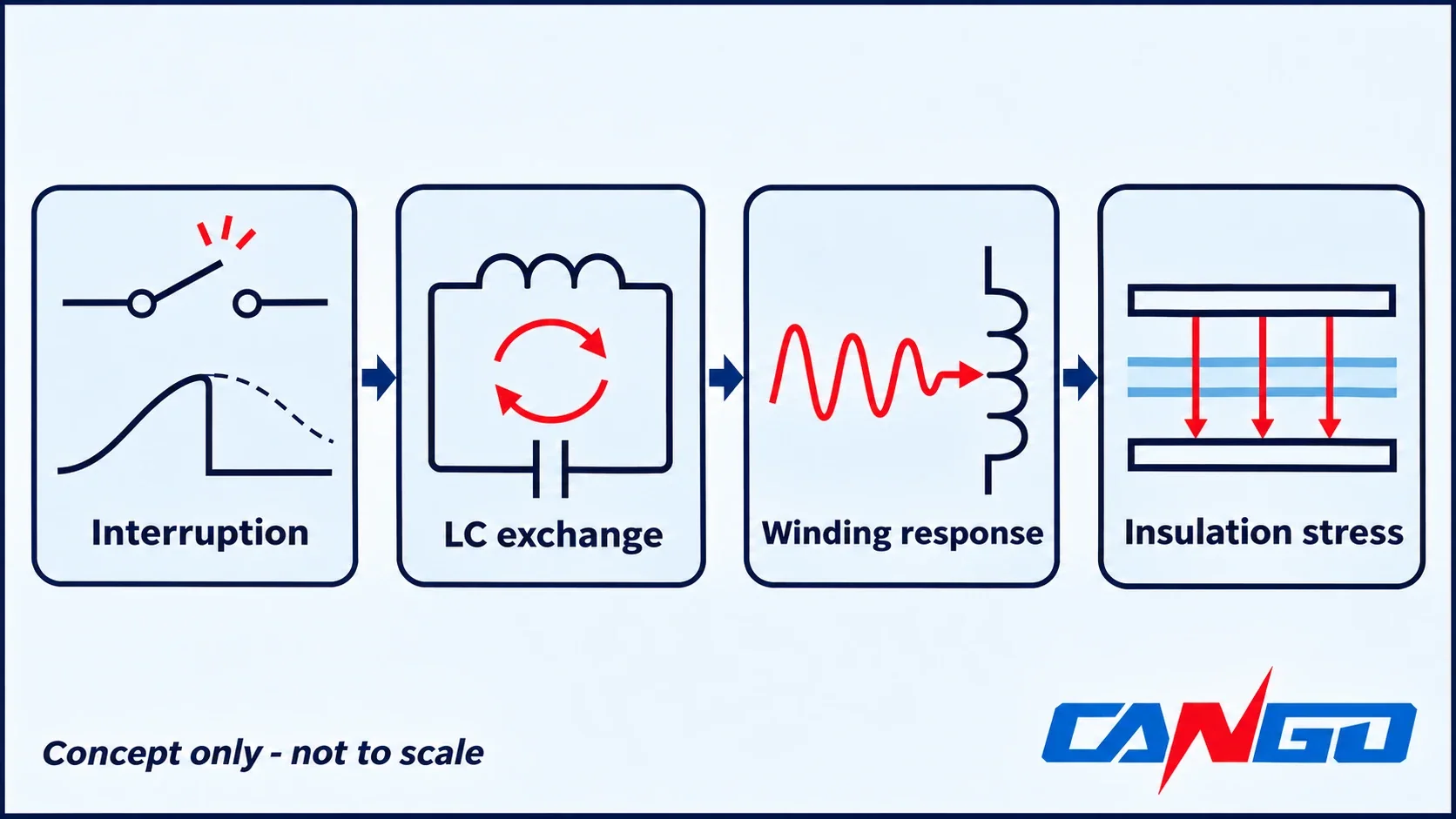
Next, energy stored in winding inductance exchanges with the connected capacitances. That exchange can produce a high-frequency oscillatory voltage with a steep wavefront (high dv/dt). If its frequency content excites a winding natural frequency, the internal voltage distribution can become much more severe than the terminal reading suggests. Turn-to-turn or section-to-section insulation can be overstressed; a terminal-to-earth flashover may also be reported. [1,2]
| Stage | What happens | Possible evidence, not a diagnosis |
|---|---|---|
| Interruption initiates the event | Small inductive current is chopped; closing discharges or opening reignitions may launch further disturbances | Operation timing and suitably captured voltage/current records |
| Stored energy redistributes | Winding inductance and system capacitance exchange energy | An oscillatory terminal waveform, if adequate measurement exists |
| A fast wavefront reaches the winding | Frequency content interacts with the winding response | A terminal record requiring comparison with transformer response information |
| Local insulation sees stress | Resonance-sensitive internal gradients can overstress turns or sections | Switching-correlated winding damage or terminal flashover requiring investigation |
This sequence explains why the investigation needs the breaker, cable and transformer together. A breaker inspection alone cannot establish the winding response, and a transformer nameplate cannot describe the complete switching event. Do not convert an ordinary relay event log into a claimed high-frequency waveform measurement.
Why dry-type transformers take the hit
A terminal voltage is a boundary condition, not a map of the voltage between every turn and winding section. The transformer’s frequency-dependent response determines how an applied disturbance distributes internally. Near a natural frequency, local electrical stress can be amplified even when the observed terminal magnitude appears acceptable.
Internal overstress can occur with terminal voltage below the arrester’s protective level and below the terminal BIL. Basic impulse insulation level describes a specified terminal impulse withstand; it does not prove acceptable internal response to every oscillatory switching waveform. Consequently, “the arrester operated normally” and “the BIL is adequate” do not, by themselves, exclude switching-related insulation damage. [1]
The evidence discussed here concentrates on dry-type transformer applications. That focus does not establish that every dry-type design is vulnerable or that oil-filled equipment is immune. Assess the actual winding design, connected capacitance, loading and switching behavior. Use the SCB family comparison for product-selection context; a family designation is not a transient-performance assessment.
The Eng-Tips discussion “SF6 Breaker Voltage Transient Failures” is a useful boundary check. The original poster reported that closing an SF6 breaker onto an unloaded transformer on a 27.6 kV bus coincided with terminal-to-earth flashover at a nearby, loaded dry-type transformer. This was not a vacuum-breaker case and is not a CANGO installation report. [3]
Replies discussed snubbers and the limitations of relying on arresters. Treat that as an attributed practitioner report, not a measured causal study: the thread does not establish the precise waveform or prove a particular resonance mechanism. Its practical lesson is to investigate the switching interaction without assigning the event to the wrong breaker technology.
Arrester vs snubber
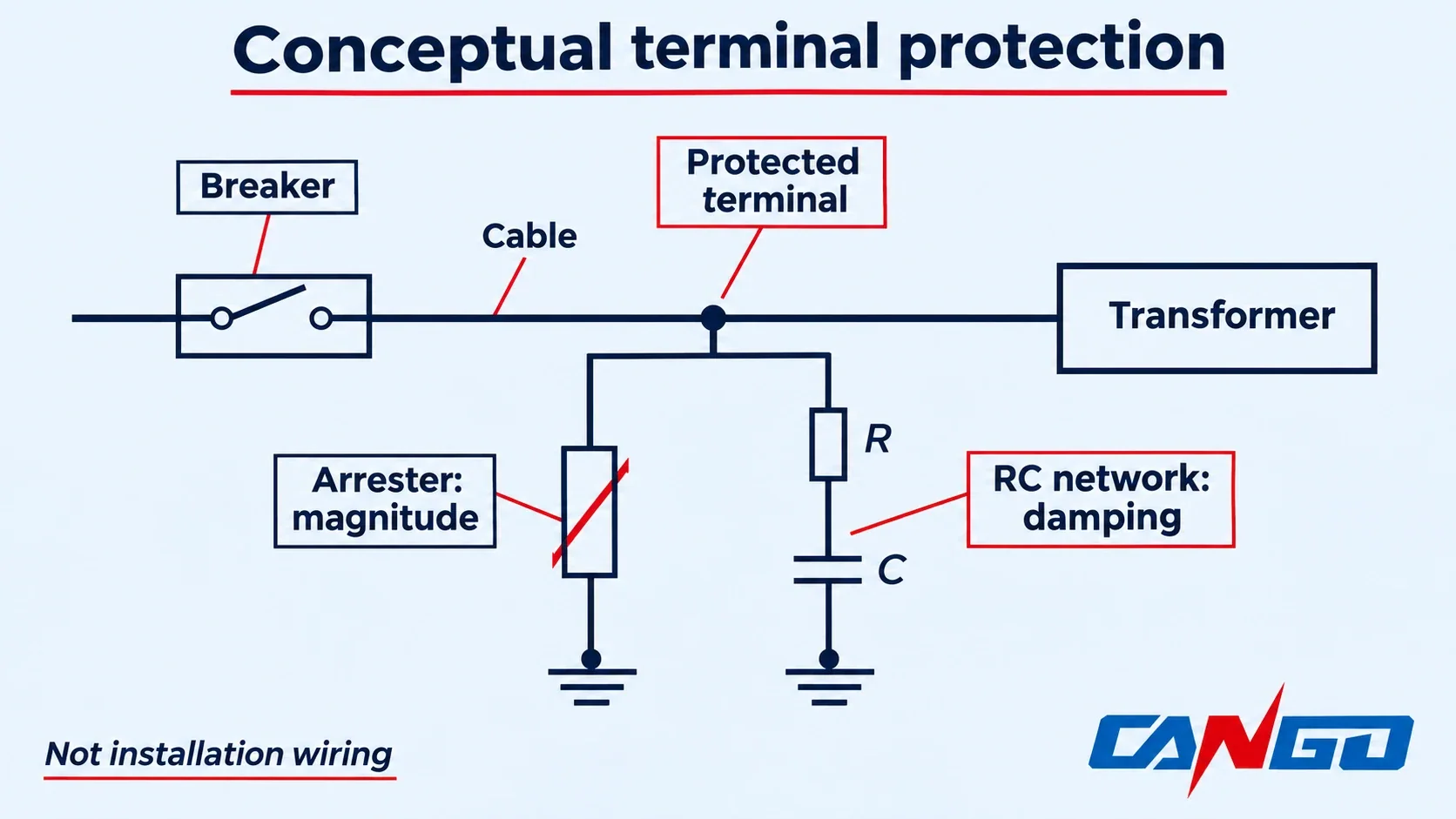
A surge arrester provides nonlinear terminal-overvoltage limiting and an energy-discharge path to earth. Its protective level answers a magnitude question. It should not be credited as a designed frequency-shifting and damping network merely because it is installed near the transformer.
An RC snubber is a resistor-capacitor network designed for the connected system. Its capacitive branch changes the high-frequency circuit response; resistance dissipates energy and damps oscillation. A design objective can be to move troublesome transient content below a relevant winding resonance and reduce the applied wavefront. Whether that objective is achieved must be evaluated, not assumed from the presence of a capacitor.
| Comparison | Surge arrester | RC snubber |
|---|---|---|
| Principal target | Terminal-to-earth overvoltage magnitude | Oscillatory response, frequency content and damping |
| Magnitude limiting | Clamps according to its characteristics and application | Can reshape the transient; not a substitute for arrester coordination |
| Frequency and damping | Does not establish tuned frequency or damping control | Selected capacitance and resistance shape and damp the response |
| Typical project location | At the protected equipment, as specified by insulation coordination | At transformer terminals or the breaker load side, as established by the design |
| Application basis | Requires correct arrester selection and connection | Requires system-specific network selection and location review |
| What installation alone proves | That an arrester is present, not that internal stress is acceptable | That components are present, not that the network is correctly designed |
The devices are complementary. “Not just a surge arrester” does not mean remove the arrester and install an arbitrary snubber instead. Retain the required magnitude protection while assessing whether additional waveform control is necessary. Nor should a bare surge capacitor be described as an equivalent damped RC network without evaluating its effect. [1-3]
The conceptual branch arrangement below shows the functional distinction. Actual phase connections, protection, earthing, component construction and installation details belong in the approved project documents. Position and connection affect the result; an available enclosure is not automatically a suitable location.
When to run the assessment
Use the following conditions as reasons to request review. They are not numerical pass/fail rules, and no single item proves that a snubber must be installed.
Light-load or no-load transformer switching
Identify whether the breaker interrupts predominantly magnetizing current rather than a heavily loaded transformer. Stored inductive energy and the available capacitance can then be an important combination. Capture the actual load state for the operation under review; the same feeder under a different load is not necessarily the same transient problem. The “Use of Snubbers” discussion describes this concern as practitioner experience, not a universal design formula. [2]
Dry-type winding response not established
Ask whether the transformer supplier has evaluated the specified switching environment and what information supports that answer. An insulation-class label or a satisfactory routine test report does not answer the frequency-response question. The appropriate outcome may be additional data, a system study or written confirmation with stated assumptions, rather than immediate component purchase.
Short breaker-to-transformer cable
Short cable and relatively little connected capacitance recur in the concerns discussed by practitioners. Record the real cable route and construction rather than using equipment-room proximity as the model. Do not invent a safe cable-length threshold: long cables can also participate in oscillatory behavior, and a larger capacitance does not eliminate every possible interaction. [1,2]
Frequent switching
Record normal operations, tests and transfer operations, including light-load states. More opportunities for a troublesome interaction justify closer review, but do not establish a universal permissible operation count. A motor start/stop or capacitor-style switching duty needs its own load-specific assessment; it is not permission to transfer the transformer’s snubber design to another feeder.
Damage correlated with switching
Preserve event timing, loading, which device operated, damage location and any available records before replacing equipment. A correlation is an investigation trigger, not proof that the breaker is defective. Use the general switchgear failure guide for the separate broader fault scope. Keep any GIS gas/partial-discharge investigation distinct from this switching-interaction question.
In “Use of Snubbers”, contributor prc wrote “normally snubbers are not required with 5kV VCB” and “may be required above 11kV and esp with dry type transformers”. That is an attributed practitioner view, not a standard threshold. It cannot establish that lower-voltage feeders need no attention or that all higher-voltage feeders require snubbers. Another contributor explicitly rejected a simple rule of thumb. [2]
Motor feeders: same question, thinner evidence
Motor feeders deserve a separate set of questions, not a conclusion copied from a transformer case:
- What inductive load and operating state does the breaker interrupt?
- Has the motor or breaker manufacturer identified a small-current interruption concern for that duty?
- How frequent are starts, stops and test operations?
- What are the actual cable length, type and terminal arrangement?
- Is there a history of terminal flashover or insulation damage associated with switching?
- What motor-specific information supports the proposed protection and any additional network?
The transformer-interaction guide is not a universal motor-protection design method. Its scope excludes transformer applications with certain inductive loads, including stalled or accelerating motors, that are addressed elsewhere. Therefore, motor-feeder protection requires separate confirmation by the motor/breaker manufacturers or an appropriate transient study. [1]
This article assigns no motor switching limit, RC values or protection guarantee. A motor feeder appearing in the title or triage table is an instruction to ask the right questions, not evidence that it requires the same network as the adjacent dry-type transformer.
What to specify and ask for
Turn the assessment request into a defined engineering deliverable before equipment release or commissioning. A statement that the feeder “has arresters” is not a complete answer to the interaction question.
- Request an assessment or written technical confirmation. Identify the proposed switching operations, relevant load states and the required conclusion. Ask what assumptions support either an additional mitigation design or a decision that no snubber is needed. Keep the result tied to the actual feeder configuration.
- Provide breaker information. Give the exact device type and available opening, closing, chopping and reignition characteristics. Obtain relevant information from the manufacturer; do not substitute a generic current or an assumed ideal switch in place of missing data.
- Provide cable and transformer information together. Include cable type and route length, connected equipment, transformer construction, declared insulation/BIL information and available frequency-response or transient-model information. Supply load states, switching frequency and the event history. Nameplate information alone does not supply the full model.
- Assign network design and supply responsibility. If mitigation is required, the responsible designer must select the RC network and demonstrate its intended effect for the system. State who designs, supplies, reviews and accepts it in the technical agreement. Do not assume that ordering a switchgear lineup or transformer includes those responsibilities.
- Reserve a feasible installation position. Ask the equipment suppliers to confirm space and compatible interfaces at the intended transformer-terminal or breaker-load-side location. Allow for possible later addition where the project requires it, while recognizing that a reserved space does not prove electrical effectiveness or installation acceptability.
- Preserve the design after commissioning. Record the accepted configuration and assessment assumptions. Changes to breaker, cable or transformer require review of the original conclusion. Carry approved inspection and documentation requirements into the switchgear maintenance plan.
- Investigate failed feeders before repeating the event. Establish switching correlation and the condition of affected equipment before selecting replacement parts or authorizing further operation. Do not repeatedly energize a damaged transformer to reproduce a fault. Qualified personnel and the responsible project engineer determine the investigation and return-to-service plan.
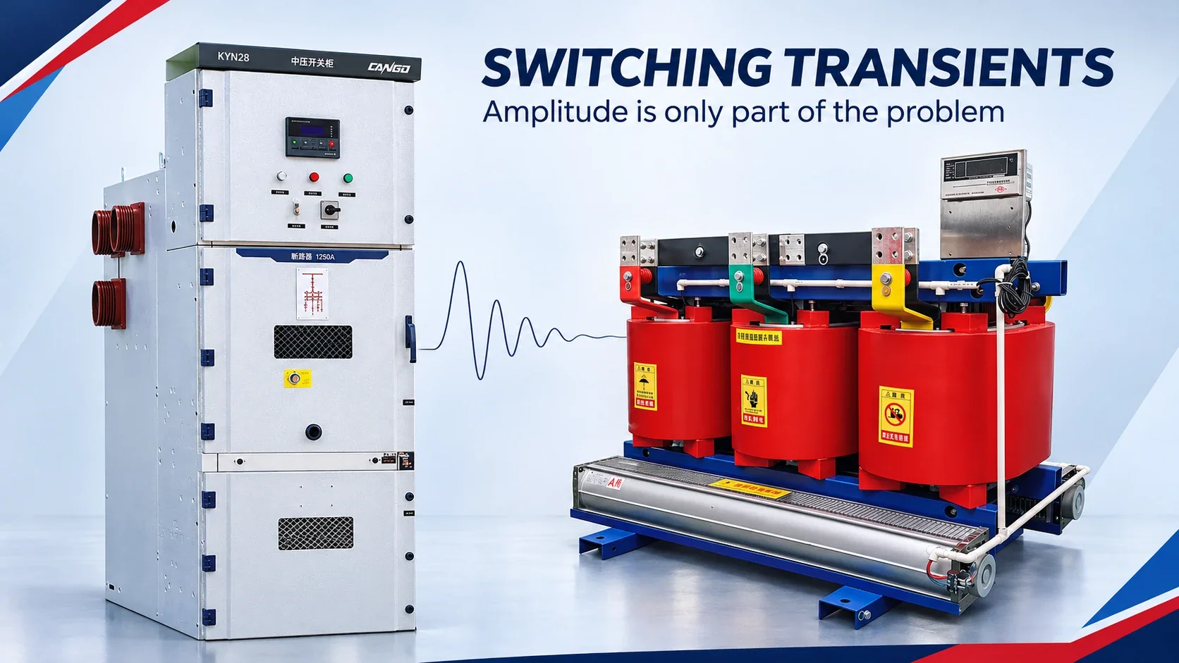
For CANGO equipment, the relevant inquiry is the interaction between a documented vacuum-feeder configuration, such as KYN28-12, and an SCB dry-type transformer, such as SCB10. The product pages establish those equipment families, not an installed system’s transient behavior. [4,5]
Ask the buyer’s design team and equipment suppliers to resolve the assessment and installation interfaces in the technical agreement. This is a project design item, not a claim that CANGO supplies RC snubbers, arresters or transient-study services. The SF6 forum example remains a separately attributed non-CANGO report.
FAQ
Does every vacuum circuit breaker need a snubber?
No. Neither the assessment approach described in IEEE C57.142-2010 nor the presence of a vacuum breaker establishes a universal installation requirement. Review the transformer, cable, loading, switching duty and history together. A supported conclusion may be that no additional snubber is needed; another feeder may require a designed network. “Every VCB needs one” and “a VCB never needs one” both skip the system-specific decision. [1,2]
We already have surge arresters. Why did the transformer still flash over?
An arrester’s terminal-magnitude protection does not establish control of the oscillatory waveform or the winding’s internal response. Local insulation stress can be unacceptable even when terminal voltage is below the arrester protective level or terminal BIL. If flashover coincides with switching, investigate that interaction alongside the actual equipment condition. The timing does not, by itself, prove the cause or justify changing protection without assessment. [1,3]
Where is an RC snubber installed?
Possible locations include the transformer terminals or the breaker load side, as established by the system design. Placement and connection influence what the network does, so proximity or available mounting space alone is not enough. The approved documents must define the actual arrangement and responsibilities. The conceptual figure in this article illustrates complementary branches, not instructions for connecting a particular cabinet or transformer.
Can you give standard RC values for the snubber?
No universal component values can be selected from this article. The network must suit the actual switching device, cable, transformer response and operating conditions. The designer must establish suitable components, ratings, location and the intended damping or frequency-shifting effect. A catalogued assembly may be considered only after its suitability is confirmed for the system. Buying an arbitrary resistor and capacitor does not complete that assessment.
What information does an assessment need?
Provide the breaker type and available interruption characteristics; cable length, type and arrangement; transformer construction, insulation/BIL data and available response information; load states and switching frequency; and previous damage or flashover records. Identify which device operated and what other equipment was connected. Ask the responsible engineer or suppliers to specify missing inputs rather than replacing them with generic values. The requested output is a documented decision, not merely a component list.
Sources
- [1] IEEE Std C57.142-2010, IEEE Guide to Describe the Occurrence and Mitigation of Switching Transients Induced by Transformers, Switching Device, and System Interaction. Historical Guide and assessment framework; previously Inactive-Reserved, now listed by IEEE as superseded by C57.142-2025. Scope, purpose and publicly visible preview material were consulted; no full-standard design calculation is reproduced.
- [2] Eng-Tips, Use of Snubbers, discussion begun July 19, 2013. Practitioner views and assessment context; not a source of standardized voltage thresholds or component values.
- [3] Eng-Tips, SF6 Breaker Voltage Transient Failures, discussion begun February 2, 2010. Attributed SF6-breaker incident report and practitioner responses; not a verified waveform study.
- [4] CANGO product information, KYN28-12 metal-clad switchgear, checked November 10, 2026; vacuum-feeder equipment context only.
- [5] CANGO product information, SCB10 dry-type transformer, checked November 10, 2026; product construction context, not a transient-protection guarantee.