Short answer: Connection overheating, insulation deterioration and breaker mechanism/control problems are three recurring groups of switchgear faults. Start with the observed symptom in the navigation table, then follow the relevant checks before ordering replacement parts. Infrared hot spots, discharge indications, slower operation and inconsistent status signals can provide early warning. Investigating those signs early can limit damage and emergency repair scope, although the actual outcome depends on the defect.
Short safety note: Medium-voltage inspection and repair must be performed by qualified, appropriately licensed personnel after isolation, proving dead and applying the required earths under the site permit process. Identify all supplies, backfeeds and stored-energy hazards before work starts. This article is a diagnostic planning guide, not a replacement for manufacturer instructions or site procedures. It contains no energized-work method; references to thermal or online monitoring mean existing records or approved monitoring provisions.
1. Start from the symptom
The same trip can originate in protection, a mechanism, insulation or control power, and several defects can interact. Preserve relay records, alarm timestamps, load information and the last successful operating record before components or settings are changed.
| Symptom | Most likely cause | First check | Section |
|---|---|---|---|
| Hot spot or burning smell | Loose/oxidized connection, overload or restricted cooling | Existing infrared records, phase comparison and circuit loading | §2 |
| Insulation alarm, earth-fault trip or tracking | Moisture, contamination or damaged insulation | Insulation resistance against baseline/manufacturer values; PD records where fitted | §3 |
| Breaker will not close | Control supply, closing circuit, interlock or unreset mechanism | Supply, closing circuit, then mechanism/truck position | §4 |
| Breaker will not open or opens slowly | Trip circuit, coil, mechanism wear or hardened lubricant | Trip path, operation counter and mechanism condition | §5 |
| Trip without an obvious process fault | Settings mismatch, CT circuit problem or inrush response | Event record, approved settings, CT ratio/polarity and secondary circuit | §6 |
| Abnormal sound/vibration or inconsistent local indication | Auxiliary-contact/indication problem; possible CT or other electrical defect | Correlate sound/event records, supply and position feedback | §7A; CT-related trips: §6 |
| Lamps out, remote command fails or interlock blocks movement | Indication supply, auxiliary contacts, command logic or interlock state | Control supply, feedback and documented interlock logic | §7A/§7B |
| Condensation or corrosion | Failed heater, ventilation problem or failed seals | Heater status, moisture evidence, door and gland seals | §8 |
A symptom may cross rows: complete the first checks before concluding which component failed. A rating or configuration mismatch can also contribute to faults; use Medium-Voltage Switchgear: Types, Ratings and Selection Guide when checking whether the installed arrangement suits the duty.
2. Overheating and hot spots
Symptom: A recorded infrared survey shows a joint on one phase hotter than comparable joints on the other phases. Discoloration, a burning smell, softened insulation or damaged contact surfaces may accompany it. Visible damage means the affected circuit needs assessment, not another operating trial.
Likely causes: A loose, oxidized or damaged busbar joint, cable termination or breaker terminal can increase connection resistance. Overload and obstructed ventilation are separate possibilities. A localized joint problem and a cooling problem can coexist, so replacing a breaker may leave the cause untouched.
What to check: First compare thermal records at comparable loading and confirm which joint was observed; different loads or viewing conditions can mislead. Next compare circuit loading with the installed rating. Under the approved outage, inspect the identified connection, surrounding insulation and ventilation path, then assess the suspect conductive path against manufacturer values and baseline records. No universal temperature difference is assumed.
Fix: After isolation, use the manufacturer’s contact-surface preparation and joint procedure. Clean suitable contact surfaces, tighten only as specified using the prescribed torque, and replace burned connectors or damaged insulation. Do not polish away required plating or treat every connection as needing retightening. Verify the repaired path and address overload or cooling restrictions before release.
Prevention: Correct the specific joint, loading or airflow problem; use Medium Voltage Switchgear Maintenance: Inspection Checklist and Intervals for thermal follow-up and manufacturer-directed connection checks, without inventing a routine retightening rule.
3. Insulation failure and partial discharge
Symptom: An earth-fault trip, insulation alarm, visible tracking or abnormal installed partial-discharge monitoring points toward insulation distress. Crackling or an unusual discharge odor may be associated evidence. None identifies the exact failed component on its own.
Likely causes: Moisture and contamination can affect insulation surfaces; cracking, aging-related deterioration or installation damage can compromise the insulation itself. A damaged cable termination may present as a cabinet fault. Trace the affected circuit rather than assuming the entire assembly is defective.
What to check: Preserve alarm and trip records, then inspect the isolated affected area for contamination, cracks, erosion and water paths. Compare insulation-resistance results with applicable manufacturer requirements and commissioning or accepted baseline values under comparable conditions. Where PD monitoring is fitted, review its location-specific records and trends. PD is not standard equipment on every cubicle, and a clear record does not replace inspection.
Fix: Clean and dry suitable surfaces using the approved method, replace punctured or cracked insulation and investigate adjacent damage. Find the source of moisture or installation stress before return to service. A better resistance reading after drying does not prove that tracking or internal damage has been removed.
Prevention: Record the contamination and moisture source for corrective follow-up; Medium Voltage Switchgear Maintenance: Inspection Checklist and Intervals covers the preventive program. Apply checks to the actual insulation arrangement described in Air-Insulated vs Gas-Insulated Switchgear: Which Should You Choose?; sealed compartments are not opened for routine cleaning.
4. Breaker will not close
Symptom: A close command produces no movement, or the breaker closes and immediately opens. Preserve the sequence of indications and relay events. Immediate opening may be an intentional protection response, not a failed closing mechanism.
Likely causes: Separate three paths. The control-power path includes lost supply, insufficient voltage and a blown control fuse. The closing-circuit path includes the closing coil, contactor, auxiliary contacts, wiring and an incorrectly positioned selector. The mechanism/interlock path includes incomplete spring charging, an unreset mechanism, an unsatisfied interlock or incorrect withdrawable-truck position.
What to check: Follow an electrical-before-mechanical order: supply evidence first, the closing circuit against its schematic next, then mechanism and interlock status. Qualified personnel use the manufacturer’s isolated diagnostic arrangements to assess supply and circuit condition. On withdrawable equipment, compare the verified truck position and position contacts with the permitted operating state. Do not infer a healthy supply from a single illuminated lamp.
Fix: Correct the supply defect and establish why a fuse failed before fitting the specified replacement. Replace a defective coil or contactor only with the manufacturer-approved type, then verify affected wiring and auxiliary contacts. Mechanism resetting, lubrication and adjustment follow the manufacturer instructions. Do not repeatedly issue close commands to force an unresolved condition.
Prevention: Retain the failed-path finding in the work order so the next diagnosis starts with evidence. The assembly’s insulation medium does not identify its operating mechanism; see Vacuum Circuit Breaker vs SF6 Circuit Breaker: How the EU F-Gas Rules Change the Choice for the separate interruption-medium context.
5. Breaker will not open, or opens too slowly
Symptom: An opening command has no response, or measured opening behavior has deteriorated from the accepted record. A changed sound or incomplete position indication may be additional evidence. Failed opening is a safety-critical fault: take the affected circuit out of service through the authorized site process and do not continue operating with the defect.
Likely causes: A defective trip coil, interrupted trip circuit or control-supply problem may prevent release. Worn parts, weakened springs, hardened lubricant or binding after accumulated operations may prevent the mechanism completing its movement. A healthy coil does not prove the mechanism is healthy.
What to check: Review the trip command and circuit records, then assess the trip path and coil using the manufacturer procedure under controlled isolation. Record mechanism operation count and visible condition. Compare the prescribed mechanical-characteristic results with manufacturer limits and commissioning or accepted baseline records, including relevant control-supply conditions.
Fix: Replace the confirmed failed coil or worn components and perform only manufacturer-specified lubrication and adjustment. Stored-energy mechanisms require qualified, appropriately licensed personnel following the manufacturer manual or referral to the manufacturer for repair. This guide does not describe dismantling a spring mechanism. Demonstrate acceptable operation and resolve the cause before an authorized release.
Prevention: Keep the operation record, mechanism findings and repaired components identifiable. Review recurrence against actual duty rather than treating a successful opening test as proof that the underlying wear or supply issue has disappeared.
6. Tripping with no real fault
Symptom: Protection trips the circuit, but no short circuit or overload is apparent afterward. Describe this initially as an unexplained trip: a transient fault may have cleared before inspection. Preserve event records and disturbance waveforms before changing settings.
Likely causes: Protection settings may not match the approved study or may be outdated after network changes. Incorrect CT ratio or polarity, poor secondary connections or an open secondary circuit can distort the protection input. Transformer energization or motor-starting inrush can also expose a coordination or application problem.
What to check: First identify the operated element and compare the event sequence with loading and switching history. Then compare the active setting file with the approved settings and current system study. Verify CT identity, ratio, polarity and secondary-circuit arrangements against drawings using approved isolated checks. A CT secondary must never be left open while primary current flows. No secondary-circuit alteration is an energized diagnostic shortcut.
Fix: Adjust settings only following an authorized setting/coordination review; do not invent a higher pickup or delay to suppress trips. Correct CT wiring, connection or component defects with the affected circuits safely isolated. Confirm that the intended protection response is restored before release. For transformer-feeder protection choices, refer to RMU Transformer Protection: Switch-Fuse vs Circuit Breaker rather than assuming every nuisance trip needs a new protection architecture.
Prevention: Keep the approved setting revision, CT details and event evidence together, and update the engineering review when system duty changes. This prevents the same mismatch being reintroduced after repair or configuration work.
7. Control power, indication and interlock faults
This section addresses indication and permissive logic themselves. Closing- and tripping-circuit diagnosis belongs in Sections 4 and 5. If sound or vibration accompanies an electrical alarm, investigate that circuit too; a lamp defect is not a sufficient explanation.
7A. Local indication and auxiliary-contact faults
Symptom: A lamp is out or indicated position conflicts with the recorded operation
Likely causes: lost indication supply, a failed indicator or defective auxiliary feedback.
What to check: Compare the supply/fuse evidence and isolated auxiliary-contact/indication circuit with the drawing, correlating any sound or vibration with electrical events.
Fix: Replace the confirmed failed indication component or approved auxiliary-contact assembly and verify feedback
Prevention: retain the corrected wiring/feedback record rather than treating a restored lamp as proof of primary position.
7B. Remote control and interlock faults
Symptom: Remote commands receive no response or an interlock prevents permitted access/movement
Likely causes: an incorrect selector state, missing feedback, logic mismatch or mechanical binding.
What to check: Review command/event records, then compare isolated auxiliary feedback and verified interlock positions with the documented permissive logic.
Fix: Correct the confirmed control, contact or mechanical defect by the approved method
Prevention: verify the intended permitted and prohibited states before release, because an interlock is a safety device against incorrect operation and must not be bypassed or removed to obtain movement.
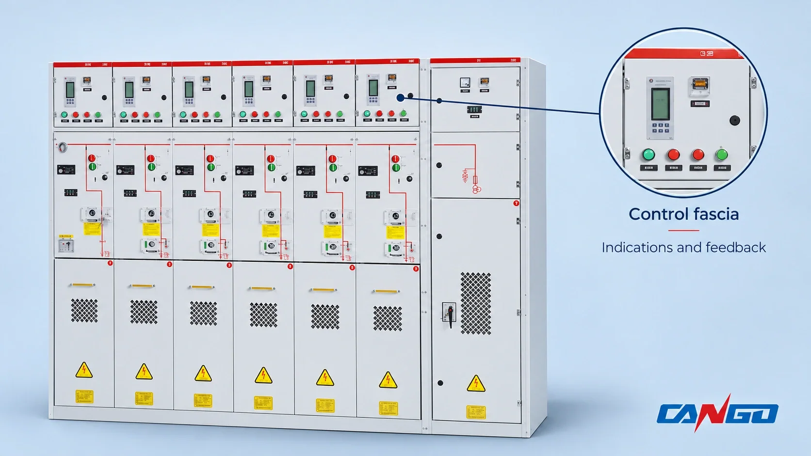
8. Moisture, condensation and corrosion
Symptom: Condensation, corrosion, damp deposits or a heater alarm appears inside the cubicle. Staining below a cable entry or door seal can help locate a water path.
Likely causes: A failed heater or its supply/control circuit, obstructed ventilation, damaged door seals or failed cable-entry sealing can combine with high environmental humidity. Replacing a heater alone will not correct water entering from a trench or damaged enclosure.
What to check: Under the approved isolation arrangements, assess heater condition and its circuit against the manual, review available humidity records and inspect door/gland seals. Trace moisture from the affected surface toward likely entry points. Check whether corrosion has damaged terminals, mechanisms or insulation supports, linking findings to Sections 2 and 3 where relevant.
Fix: Replace defective heaters with the specified type, restore their intended supply/control function and repair the confirmed sealing or ventilation defect. Clean and dry affected areas by the approved method, replacing parts damaged beyond recovery. Establish that the moisture source and resulting electrical damage have been addressed before re-energization.
Prevention: Carry the identified water path and heater defect into Medium Voltage Switchgear Maintenance: Inspection Checklist and Intervals for follow-up. This diagnosis does not set a new inspection interval or substitute drying for insulation acceptance.
9. Repair or replace: how to decide
| Situation | Repair | Replace |
|---|---|---|
| One failed component; approved parts available; cubicle sound | Replace the component and verify affected functions | Not justified by that component failure alone |
| Same fault recurs after repair | Investigate settings, environment, duty and the previous diagnosis | Consider replacement if the underlying defect cannot be corrected reliably |
| Insulation or enclosure damage extends beyond one component | Obtain an assembly-level damage assessment | Replace affected sections or assembly if integrity cannot be restored and verified |
| Parts unavailable or mechanism worn beyond permitted adjustment | Do not improvise incompatible parts or unauthorized adjustments | Plan a compatible replacement with engineering review |
| Safety failure: breaker fails to open or interlock defeated | Remove from service; correct and verify safety functions first | Replace if dependable safety function cannot be restored |
Base the decision on recurrence, approved-parts availability and safety together. Neither the apparent size of a defect nor one successful test determines whether the assembly should remain in service. Record the diagnosed cause, repair scope, verification results and release authority; do not make a repair-versus-replace claim from an invented price, saving percentage or service-life number.
10. CANGO ranges
The diagnostic categories apply according to the installed construction, not because every model shares the same failure. The following CANGO values describe selected configurations, not test thresholds or industry limits.
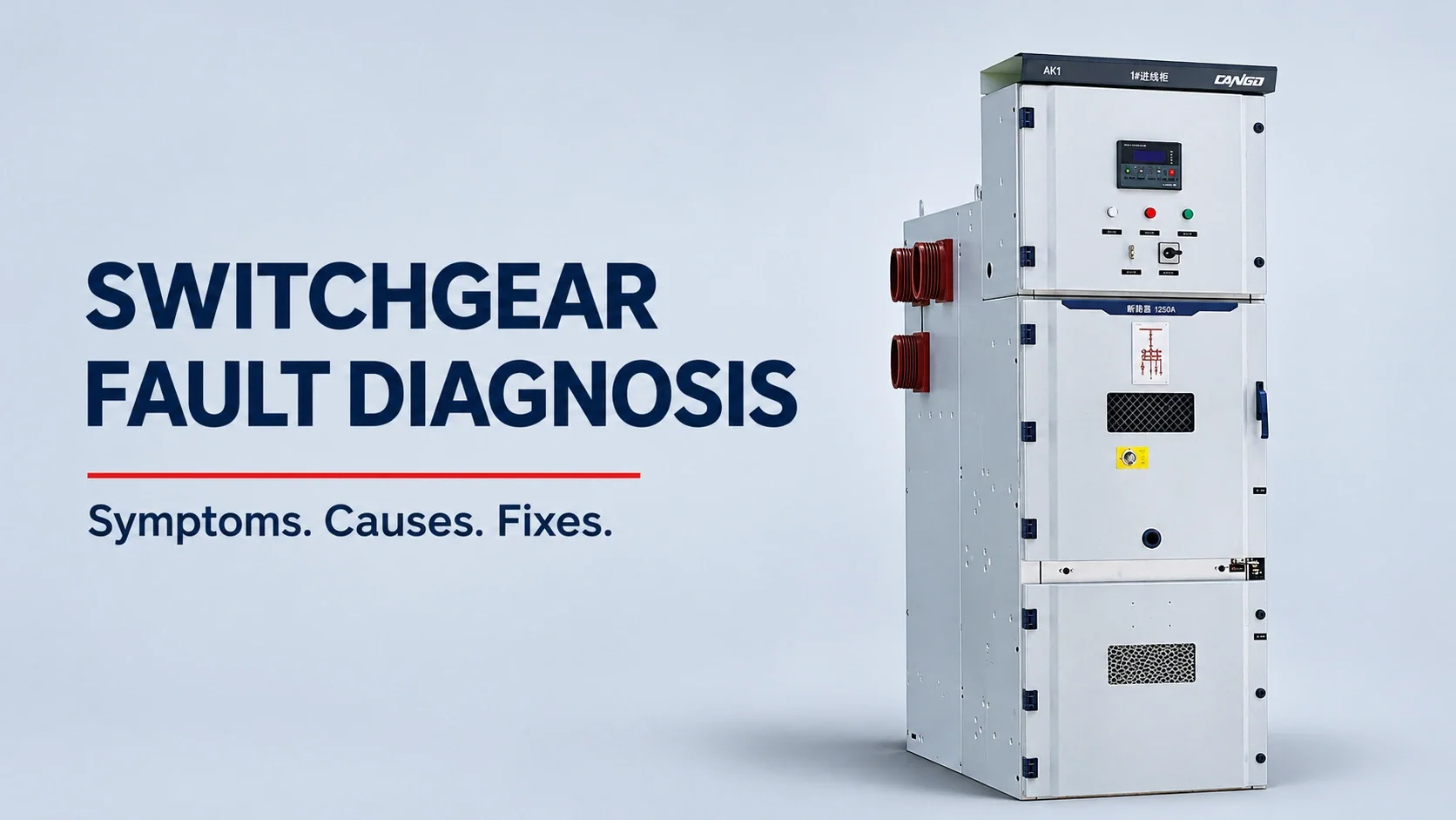
- KYN28-12 12kV Metal-Clad Switchgear: withdrawable metal-clad switchgear; breaker current 630-3150 A and short-time withstand 16-50 kA for 4 s, by configuration.
- KYN28-24: a higher-voltage panel family; diagnose against its supplied mechanism, control and assembly documents.
- KYN61-40.5: a higher-voltage switchgear family requiring its own component and arrangement records.
- XGN17-40.5: fixed switchgear; do not assume withdrawable-truck checks apply.
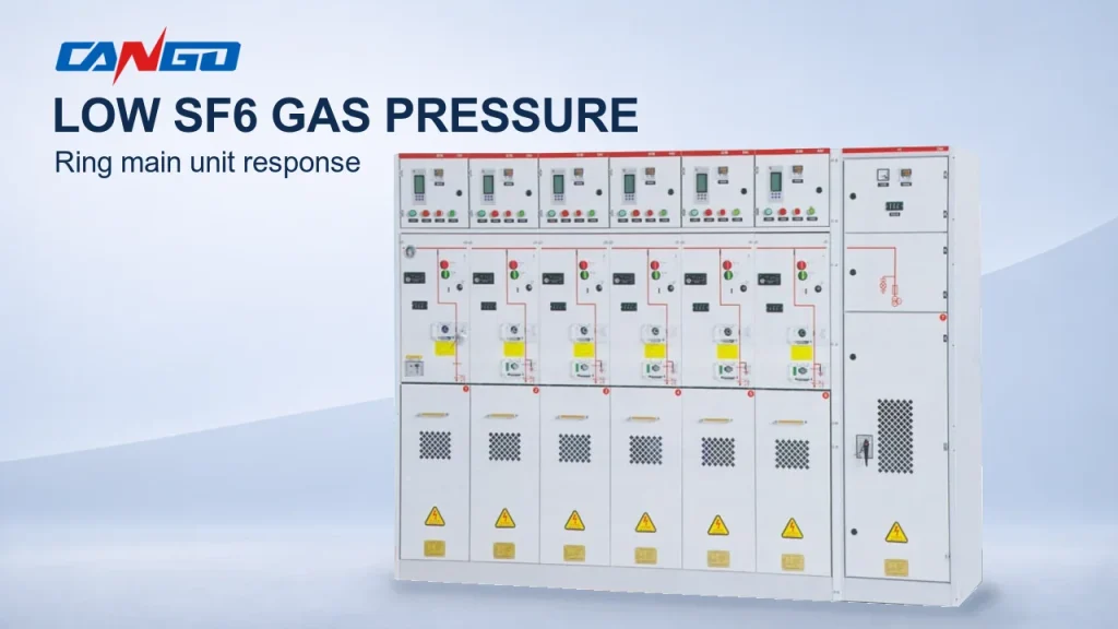
- SRM-12 12kV Gas-Insulated RMU: gas-insulated, 12 kV, ring circuit 630 A; short-circuit breaking values 20/25/31.5 kA by functional-unit configuration, not one universal ring-switch rating.
- GTXGN-12: solid-insulated, 12 kV; 630/1250 A and 25/31.5 kA breaking by configuration.
- XGN15-12: 12 kV, main bus 630 A; fuse breaking 31.5/40/50 kA by equipped configuration, not assembly withstand.
- HXGN17-12: 12 kV, load-switch current 630 A; thermal stability 20 kA for 4 s by configuration.
For the assembly-form distinction, see Ring Main Unit vs Switchgear: Differences, Costs and When to Use Each. Final configuration is confirmed against project requirements before quotation.
FAQ
What is the most common cause of switchgear failure?
There is no defensible universal ranking for every installation. Three recurring groups are connection overheating, insulation deterioration and breaker mechanism/control problems. Their common feature is that the visible symptom may have several causes: heat can involve load and contact condition, while a trip can involve protection, insulation or controls. Start with evidence and the affected circuit, then verify the diagnosis before replacing parts. No failure percentage or universal service-life figure is assumed.
Why does my circuit breaker keep tripping for no clear reason?
Treat the trip as unexplained until the event records establish what happened. Compare the operated protection element and waveform with loading and switching history, then review settings against the approved study. CT ratio, polarity or secondary-circuit defects and an inappropriate response to energization or motor starting are possible causes. Correct the confirmed issue through an authorized review and isolated repair. Do not raise settings simply to stop trips or assume no visible damage means no fault occurred.
Can an overheating connection be fixed without replacing the breaker?
Possibly, if the defect is a repairable joint and the breaker, connector and surrounding insulation remain suitable. Compare thermal records and loading, then assess the identified connection under an approved outage. Use the manufacturer’s surface-preparation and torque procedure, replacing damaged parts where required. If heating has harmed contacts or insulation, tightening alone is insufficient. Verify the repaired conductive path and resolve any overload or cooling problem before an authorized return to service.
How do I know if switchgear insulation is failing?
Possible signs include earth-fault trips, insulation alarms, tracking, cracks, discharge sounds and abnormal PD records where monitoring is fitted. These signs require investigation rather than a diagnosis from appearance alone. Under approved isolation, inspect the affected area and compare insulation results with manufacturer requirements and commissioning or accepted baseline records. Locate moisture, contamination or installation damage, and assess adjacent parts. Drying can improve a reading without correcting insulation that is already tracked, punctured or cracked.
When should switchgear be replaced instead of repaired?
Consider replacement when damage extends beyond a recoverable component, compatible approved parts are unavailable, a mechanism is worn beyond permitted adjustment, or repeated faults remain unresolved after proper diagnosis. Safety functions must be restored and verified; failed opening or a defeated interlock requires removal from service while assessed. Decide from recurrence, parts availability and safety together. A single fault, an assumed age limit or an unverified cost comparison does not establish the right replacement decision.
References
- U.S. Bureau of Reclamation, Maintenance of Power Circuit Breakers, control circuits, coils, mechanism condition and diagnostic interpretation.
- U.S. Bureau of Reclamation, Electrical Connections for Power Circuits, joint condition and manufacturer-directed connection practice.
- U.S. Bureau of Reclamation, Operation, Maintenance and Field Test Procedures for Protective Relays and Associated Circuits, protection and instrument-transformer circuit review.
- EPRI, Switchgear and Bus Maintenance Guide, insulation, environmental contamination and failure mechanisms.
- IEC, IEC 62271-200 for metal-enclosed switchgear and IEC 62271-100 for circuit breakers; publication scope only, not repair acceptance limits.
- CANGO product information: the KYN28-12 and SRM-12 pages linked above, plus GTXGN-12 Solid-Insulated Ring Main Unit, XGN15-12 12kV Ring Main Switchgear and HXGN17-12 12kV Ring Main Switchgear.