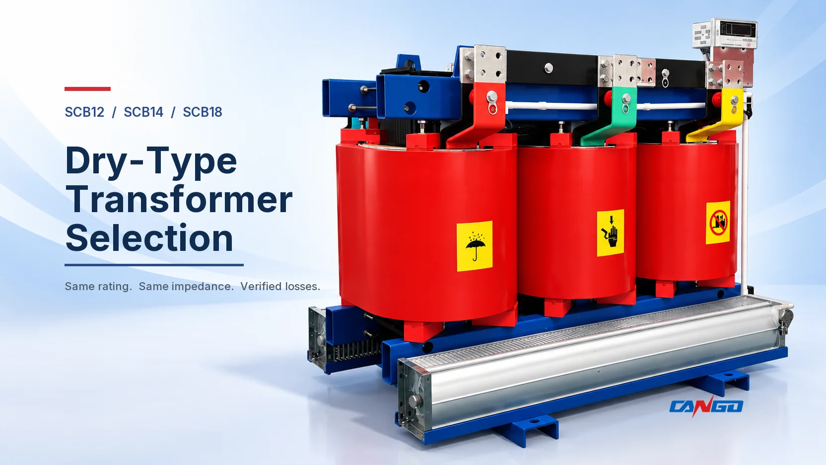
Compare the three families at the same kVA, voltage, connection and impedance. In the current CANGO tables, SCB14 and SCB18 have identical load losses at matching ratings, while SCB18 has lower no-load loss. SCB12 exposes separate B-, F- and H-class load-loss values, so its thermal configuration must be fixed before comparison. The larger model number alone does not identify the correct transformer for a project.
This guide uses the model notation SCB for readability; the linked CANGO product pages use SC(B). The conclusion is limited to the publicly visible table rows reproduced here. Final guaranteed values, tolerances, cooling, enclosure, accessories and destination requirements must be confirmed for the offered configuration.
What changes across SCB12, SCB14 and SCB18
All three CANGO families shown here cover 30 to 2500 kVA in the product tables, with Dyn11 or Yyn0 connection, 6 to 11 kV high-voltage options, a 0.4 kV low-voltage winding and similar tap ranges. Those broad similarities make the comparison practical, but they do not prove that the transformer families have the same internal construction.
| Decision field | Why it changes the comparison |
|---|---|
| Rated capacity | Loss values rise with rating; compare the same kVA rather than adjacent numbers |
| Voltage and tap range | A different winding voltage or tap requirement can change the offered design |
| Connection group | Dyn11 and Yyn0 serve different system relationships and must be fixed before selection |
| Short-circuit impedance | The same capacity can have different loss rows at different impedance percentages |
| Insulation and temperature basis | SCB12 lists B, F and H load-loss columns; the selected class must be named |
| Cooling and accessories | Fan rating, enclosure, controller and auxiliaries need explicit scope |
| Destination rules | Energy-efficiency requirements and approval routes vary by jurisdiction |
The CANGO SC(B)12 product page presents three load-loss columns. The SC(B)14-NX2 page and SC(B)18-NX1 page each present one load-loss column. That difference is a data-structure warning: a simple SCB12-versus-SCB14-versus-SCB18 table can silently compare unlike configurations.
Compare them at the same rating and impedance
The table below uses six representative rows from the current CANGO product tables. The 30, 100 and 400 kVA rows are at 4% impedance. The 630, 1600 and 2500 kVA rows use the separately listed 6% impedance versions. The SCB12 result is shown as B/F/H because the source exposes three insulation-related load-loss columns.
| Capacity and impedance | SCB12 no-load loss | SCB12 load loss, B/F/H | SCB14 no-load loss | SCB14 load loss | SCB18 no-load loss | SCB18 load loss |
|---|---|---|---|---|---|---|
| 30 kVA, 4% | 150 W | 670 / 710 / 760 W | 130 W | 640 W | 105 W | 640 W |
| 100 kVA, 4% | 320 W | 1,480 / 1,570 / 1,690 W | 270 W | 1,415 W | 230 W | 1,415 W |
| 400 kVA, 4% | 785 W | 3,750 / 3,990 / 4,280 W | 665 W | 3,590 W | 570 W | 3,590 W |
| 630 kVA, 6% | 1,040 W | 5,610 / 5,960 / 6,400 W | 885 W | 5,365 W | 750 W | 5,365 W |
| 1,600 kVA, 6% | 1,960 W | 11,000 / 11,700 / 12,500 W | 1,665 W | 10,555 W | 1,415 W | 10,555 W |
| 2,500 kVA, 6% | 2,880 W | 16,100 / 17,100 / 18,400 W | 2,450 W | 15,445 W | 2,080 W | 15,445 W |
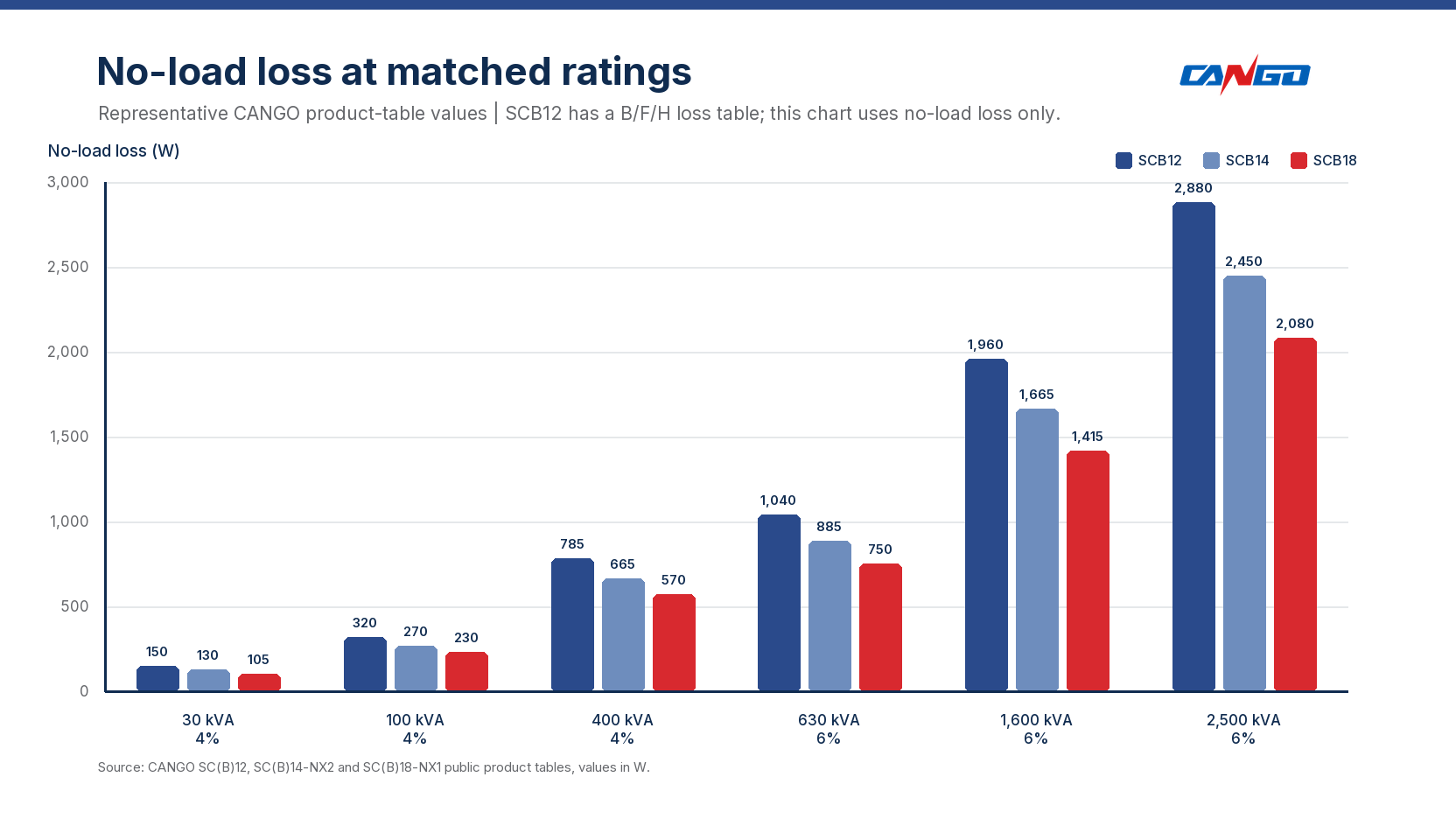
Two facts stand out. First, the visible SCB14 and SCB18 load-loss values are identical in every row shown. Second, SCB18 has the lowest no-load loss in every row. That does not automatically make one family the lowest-cost or best project choice; acquisition price, guarantees, local rules, delivery scope and actual operating time remain separate decisions.
Why SCB14 and SCB18 can match on load loss
Load loss is linked to current-carrying and stray-loss effects at a stated rating and reference basis. Matching numbers in the current CANGO tables therefore mean only that the visible SCB14 and SCB18 offers converge on the same declared load-loss result for those rows. They do not establish identical materials, dimensions, manufacturing methods or performance outside the table.
The difference appears in no-load loss. At 100 kVA and 4% impedance, SCB14 is listed at 270 W and SCB18 at 230 W, a 40 W difference. At 400 kVA the gap is 95 W; at 1600 kVA it is 250 W. These differences can be compared only because capacity and impedance have been matched.
For a simplified loss-power estimate at approximately constant voltage and frequency:
Estimated total loss = P0 + k² × Pk
Here, P0 is no-load loss, Pk is load loss at rated current and k is the operating current divided by rated current. This is a conservative magnitude model for loss comparison, not a calculation of winding temperature or permitted thermal loading. At 100 kVA and 4% impedance, applying the same load factor to both families produces:
| Load factor | SCB14 estimated total loss | SCB18 estimated total loss | Difference |
|---|---|---|---|
| No load (0%) | 270 W | 230 W | 40 W |
| 50% | 270 + 0.50² × 1,415 = 623.75 W | 230 + 0.50² × 1,415 = 583.75 W | 40 W |
| 100% | 270 + 1,415 = 1,685 W | 230 + 1,415 = 1,645 W | 40 W |
The model keeps the gap at 40 W because the displayed load-loss values are equal. The load profile still matters for the amount of total energy consumed, but it does not create a new load-loss advantage between these two rows. Replacing Pk with a thermally corrected loss value accounts for the loss variation with temperature; adding harmonic and auxiliary allowances brings the estimate closer to an energy-efficiency calculation. A project calculation should use the offered loss guarantees, actual interval loading, operating temperature, harmonics, auxiliary consumption and the contract test basis.
Turn the no-load difference into annual energy
No-load loss remains present while the transformer is energized. For an illustrative all-year schedule:
Annual no-load energy = 8,760 × P0 ÷ 1,000
At 100 kVA, SCB14 gives 8,760 × 270 ÷ 1,000 = 2,365.2 kWh per year. SCB18 gives 8,760 × 230 ÷ 1,000 = 2,014.8 kWh per year. The difference is 350.4 kWh per year when both are energized for the full 8,760 hours.
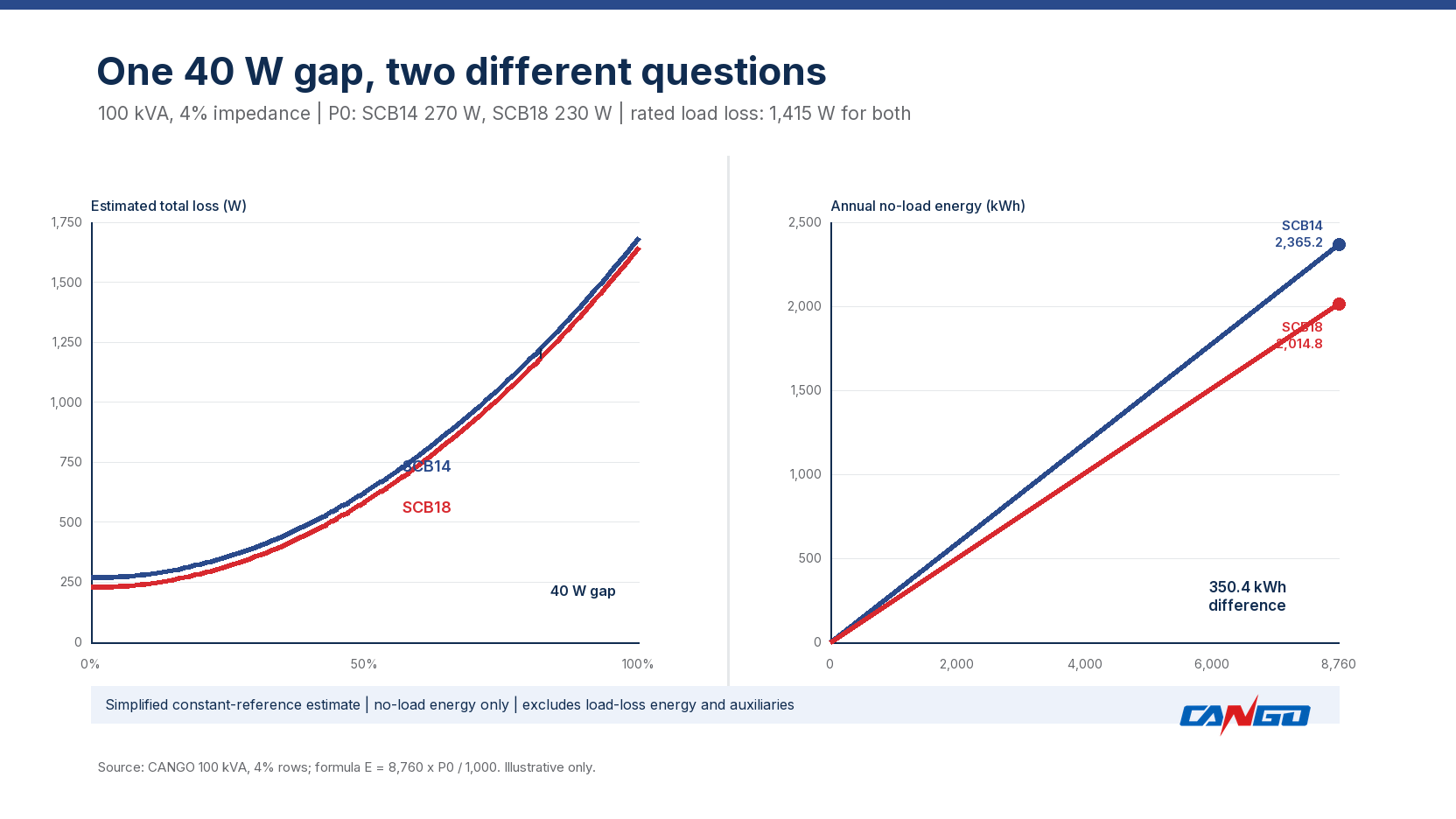
This energy value is not a payback calculation. A buyer also needs the price premium, tariff structure, discount rate, project life, loading, cooling and the cost of any associated equipment. The useful action is to put those assumptions beside the guaranteed losses rather than choosing the larger model number by habit.
Choose by the project condition, not a model ranking
SCB12 may fit when the approved design is already configured
SCB12 can be the relevant route when the project specification, existing design or approved supplier list already calls for that family. Fix B, F or H before comparing its load loss. If two bids offer different SCB12 columns, their prices and loss values are not directly comparable until the thermal configuration is aligned.
The current tables do not show a complete temperature-rise schedule or test basis for this comparison. Ask for those documents rather than inferring them from a class letter. For the relationship between the class and rise, use the separate temperature-rise versus insulation-class guide.
SCB14 may fit when the required energy class is satisfied
SCB14 can be a practical comparison point when its verified loss data and the destination energy requirement both fit the project. Do not treat the page label Level 2 as a universal certification. Match the exact destination requirement, transformer scope, rating and documentation before accepting it as compliant.
SCB18 may fit when no-load energy has project value
SCB18 is the lower-no-load-loss option in every matched row shown. That can matter where the transformer remains energized for long periods and the project evaluates no-load energy separately. It can also be relevant where a higher local efficiency class is required. Confirm the actual classification rule and the price premium; the table alone cannot prove a favorable total cost.
Compare a mixed system only after the duty is fixed
If the project has several transformers with different operating profiles, evaluate each schedule line separately. A lightly loaded, continuously energized transformer and a heavily loaded transformer with short operating hours should not be assigned the same model merely because their kVA values are close.
What to put in the transformer schedule
Use a schedule line detailed enough for every bidder to answer the same question:
| Required field | Specify this |
|---|---|
| Model family | SCB12, SCB14-NX2 or SCB18-NX1, plus any approved alternatives |
| Rated capacity | kVA, with the load calculation or design basis |
| Voltage ratio and tap range | HV and LV values, tapping requirement and operating position |
| Connection group | Dyn11 or Yyn0, including any neutral requirement |
| Frequency | 50 Hz or 60 Hz as applicable |
| Short-circuit impedance | Required percentage and tolerance |
| No-load loss P0 | Guaranteed value in W or kW |
| Load loss Pk | Guaranteed value, reference temperature and test basis |
| Insulation and temperature rise | Class, average winding rise, ambient and cooling conditions |
| Cooling and enclosure | AN or AF scope, enclosure type, ventilation and ingress requirement |
| Accessories | Fans, controller, temperature devices, terminals and monitoring scope |
| Standards and destination rules | Applicable standard editions, local efficiency requirement and approval route |
| Operating profile | Annual energized hours and expected load intervals |
| Commercial evaluation | Price, loss evaluation method, delivery and documentation scope |
The power transformer project-information guide covers the wider inquiry package. Use the kVA sizing guide if capacity is still unresolved, the oil-immersed versus dry-type comparison if the technology decision is open, the transformer impedance guide if fault current or impedance coordination drives the design, and the loss-model guide if the bidding method needs a more detailed energy calculation.
CANGO dry-type transformer options
CANGO’s Power Transformers category includes the three families discussed here:
- SC(B)12 dry-type power transformer, with B/F/H load-loss columns in the public table.
- SC(B)14-NX2 dry-type distribution transformer, described on its page as Level 2.
- SC(B)18-NX1 dry-type distribution transformer, described on its page as Level 1.
For a project review, send the transformer schedule with capacity, voltage ratio, tap range, connection group, impedance, loss limits, insulation and temperature conditions, cooling, enclosure, quantity, destination and applicable standards. Share those details through the CANGO contact page so the offered configuration can be checked against the project rather than selected from the model number alone.
References
- International Electrotechnical Commission — IEC 60076-11:2018, Dry-type transformers, official publication page and scope.
- International Electrotechnical Commission — IEC TS 60076-20:2017, Power transformers — Energy efficiency, official publication page.
- State Administration for Market Regulation of China — GB 20052-2024 official standard record, edition and effective-date record; clauses not used as global requirements.
- U.S. Department of Energy — Distribution Transformers, jurisdiction-specific energy-rule context.
- CANGO first-party product information — SC(B)12 dry-type power transformer, SC(B)14-NX2 dry-type distribution transformer and SC(B)18-NX1 dry-type distribution transformer, public product tables used for the representative values.