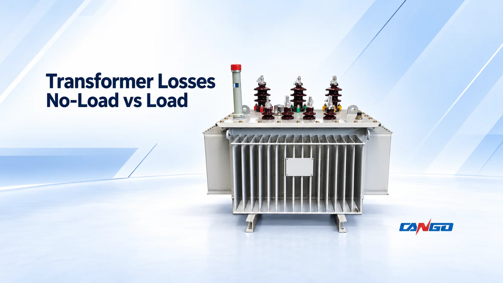
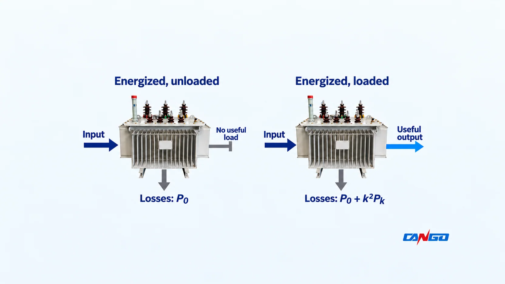
No-load loss is the power a transformer consumes while energized without supplying a load. Load loss is the additional loss associated with carrying load current. At approximately constant voltage and frequency, the first is a near-constant base; on a common temperature basis, the second increases approximately with current squared. Both contribute to the heat and energy loss of an operating transformer.
Compare both components against the intended duty. The U.S. Department of Energy technical discussion describes these dependencies and hourly loading; its U.S. regulatory requirements are not worldwide specifications.
| Question | No-load loss | Load loss |
|---|---|---|
| What drives the component? | Excitation of the energized transformer, mainly its magnetic core | Current in windings and associated stray-loss effects |
| Does it remain with no external load? | Yes, while energized | The load-dependent component falls to zero |
| How is it used here? | P0, in kW | Pk, in kW at rated current and the stated reference conditions |
| What operating input matters? | Energized hours and excitation conditions | Current magnitude in each time interval |
Do not confuse loss power in W or kW with loss energy in kWh. A 1 kW loss maintained for 24 hours consumes 24 kWh; it is not “24 kW of loss.”
Why the two losses behave differently
No-load loss: the core is still being excited
Alternating excitation repeatedly magnetizes the core. Hysteresis and induced eddy currents dissipate energy; insulated steel laminations limit eddy-current paths. Even with an open secondary, excitation current flows in the energized winding, producing a small resistive loss. Therefore “core loss” is useful shorthand, but not a claim that measured no-load loss contains nothing else. These mechanisms are explained in IIT Madras/NPTEL transformer notes, printed pages 26–27.
An idle production line does not necessarily mean an unenergized transformer. Establish the actual electrical operating schedule before deciding how many hours of P0 to include; this is an accounting input, not a recommendation to switch equipment.
Load loss: current adds resistive and stray heating
Load loss combines resistive winding heating and leakage-flux-related stray heating. The official U.S. test method, Appendix A, section 4.5, corrects the components for temperature; its reference conditions are U.S.-specific. Load loss is therefore broader than a winding-resistance calculation alone.
Calculate loss power on a clearly stated basis
For a simplified constant-reference estimate:
Loss power ≈ P0 + k² × Pk
- k is RMS load current divided by rated current on the same winding.
- Pk here means load loss at rated current, not a value already quoted at partial load.
- Near rated voltage, operating kVA divided by rated kVA approximates k. Do not substitute kW divided by rated kVA.
U.S. Appendix A, sections 5.1–5.2, supports squared-load scaling and addition of no-load loss. Use a common reference temperature, approximately rated sinusoidal voltage/frequency and ordinary balanced loading. Changing temperatures, harmonics or operating conditions requires a more detailed assessment; this calculation grants no overload permission. Cooling or control consumption outside the quoted losses needs a separate allowance.
For illustration, assume P0 = 1.0 kW and Pk = 10.0 kW. These are invented calculation inputs, not CANGO ratings, measurements or guaranteed performance.
| Current fraction k | No-load loss | Estimated load loss k²Pk | Estimated total loss |
|---|---|---|---|
| 0 | 1.000 kW | 0 kW | 1.000 kW |
| 0.25 | 1.000 kW | 0.625 kW | 1.625 kW |
| 0.50 | 1.000 kW | 2.500 kW | 3.500 kW |
| 0.75 | 1.000 kW | 5.625 kW | 6.625 kW |
| 1.00 | 1.000 kW | 10.000 kW | 11.000 kW |
At half rated current, the model gives one-quarter of the rated-current load-loss component, not one-quarter of the total. The base loss remains in the calculation.
If load loss is quoted at k_ref rather than rated current, use Pk_ref × (k/k_ref)² on a compatible corrected basis.
Equal average loading can produce different loss energy
For intervals with constant estimated loading:
Loss energy ≈ P0 × energized hours + Pk × Σ(k_i² × t_i)
Use kW and hours to obtain kWh. Equation 75 in the NPTEL efficiency chapter weights squared loading by interval duration. Average k squared is not generally the average of k².
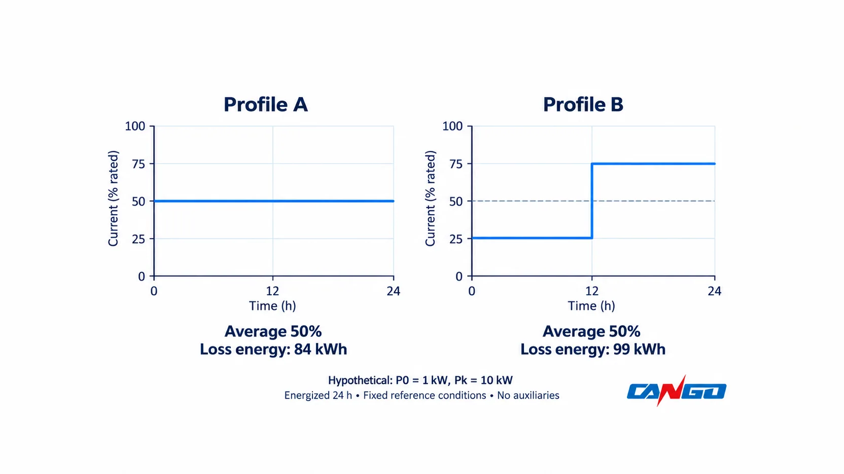
Keep the hypothetical 1.0/10.0 kW inputs and assume the transformer is energized for all 24 hours. Compare two deliberately simple schedules:
| Quantity | Profile A: steady | Profile B: variable |
|---|---|---|
| Current schedule | 24 h at 50% | 12 h at 25%, then 12 h at 75% |
| Average current fraction | 50% | 50% |
| No-load energy | 1 × 24 = 24 kWh | 1 × 24 = 24 kWh |
| Load-loss energy | 10 × 0.50² × 24 = 60 kWh | 10 × (0.25² × 12 + 0.75² × 12) = 75 kWh |
| Total loss energy | 84 kWh | 99 kWh |
Replacing Profile B with its 50% average would predict 84 kWh instead of 99 kWh: a 15 kWh underestimate for this hypothetical day. That is a consequence of the chosen inputs and squared-current model, not an observed saving or a general percentage for industrial plants.
For a real inquiry, provide interval current or kVA data, timestamps, energized periods and the rating used to normalize each interval. Mark estimated future operating cases separately from measured history. Preserve short high-current periods at a resolution appropriate to the study instead of smoothing them into one monthly average.
Loss energy is not the complete electricity bill. Time-varying energy prices, demand charges and separately supplied auxiliaries may change the economic comparison. A capitalized-loss or lifecycle-cost evaluation should use the owner’s stated financial method, not an assumed universal payback.
Efficiency needs an output-power condition
Loss is an absolute power; efficiency is a ratio:
Efficiency = output kW ÷ (output kW + loss kW) × 100%
For the same hypothetical losses, a 1,000 kVA example at 50% loading and power factor 0.9 delivers 450 kW. With 3.5 kW estimated loss, efficiency is 450 ÷ 453.5 × 100% ≈ 99.23%. This is a calculated operating point, not a product efficiency declaration.
A quoted efficiency without its loading, power factor and loss basis cannot replace P0/Pk data. Neither one efficient operating point nor a material/model label establishes the best annual result for the actual project. Capacity selection remains a separate task; see distribution-transformer kVA sizing for that workflow.
Make supplier loss data comparable before ranking offers
Ask bidders to complete the same loss schedule. This review matrix is a procurement aid, not an additional test standard.
| Data field | Clarification needed before comparison |
|---|---|
| Offered equipment | Exact configuration, rated kVA, voltage combination, frequency, connection and tap |
| Units and basis | W or kW; total three-phase value or another stated basis; rated-current or partial-load loss |
| Reference conditions | Applicable test method/edition, correction temperature, excitation basis and specified tap |
| Loss boundary | Whether cooling fans, controls or other auxiliary consumption are included or evaluated separately |
| Data status | Catalogue indication, contractual guarantee or corrected measured result for the supplied unit |
| Acceptance | Agreed tolerances, uncertainty/reporting requirements and treatment of deviations |
| Operating evaluation | The same interval-load schedule, energized hours and commercial assumptions for all offers |
Temperature correction must follow the applicable method for the loss components, not one blanket multiplier.
IEC 60076-19-1:2023 addresses uncertainty in routine no-load and load-loss measurements and corrections for known measurement-chain errors. Its public abstract does not establish a numerical acceptance tolerance for your order. Agree the applicable evidence and acceptance basis before purchase; a catalogue value alone is not a supplied-unit test result.
Reading CANGO product tables
CANGO’s S11-M oil-immersed transformer page presents losses in kW. Its SC(B)12 dry-type transformer page uses W, with separate B/F/H-class load-loss columns. Convert units first: 1 kW = 1,000 W.
The visible tables do not explicitly give the loss reference temperatures. Request those conditions rather than inferring them from a class label. Also confirm the connection-specific slash entries on applicable S11-M rows and the selected voltage-series/configuration. These are first-party catalogue entry points, not proof that one technology has lower loss for every duty. Use the separate oil-immersed vs dry-type comparison when deciding construction and installation fit.
For a loss-data review, send the offered voltage/kVA/configuration, proposed loss schedule and reference conditions, interval loading and energized hours, auxiliary boundary and applicable project requirements. The broader power-transformer project-information guide covers the remaining inquiry inputs. Ask CANGO to review the transformer loss schedule against this common basis before comparing the offers.
References
- U.S. Department of Energy — Distribution-transformer technical analysis, April 2024, prepublication document, printed pages 159 and 320–324.
- Krishna Vasudevan, G. Sridhara Rao and P. Sasidhara Rao, IIT Madras/NPTEL — Electrical Machines I, section 4: Ideal Transformer, printed pages 26–27, real-core effects.
- U.S. Government Publishing Office — 10 CFR Part 431, Subpart K, Appendix A, January 2026, sections 4.4–4.5 and 5.
- IIT Madras/NPTEL, same authors — Electrical Machines I, section 10: Efficiency, equations 71 and 75; examples here use independently chosen inputs.
- IEC — IEC 60076-19-1:2023, Rules for the determination of uncertainties in the measurement of the losses of power transformers, official scope/abstract only.
- CANGO first-party product information — S11-M oil-immersed distribution transformer and SC(B)12 dry-type power transformer, public loss-table headings and notes.