There is no universal mining power distribution design. A defensible scheme starts with the mine layout and operating zones, the incoming supply and fault study, the motor load schedule and starting duty, the required outage and switching strategy, and the environmental or regulatory boundary. Those inputs determine the mine substation arrangement, MV feeder topology, transformer ratings and LV motor-control structure.
The useful planning unit is a chain of coordinated boundaries:
incoming supply → mine substation → MV bus and feeders → transformers → LV MCC → motors
Each boundary carries electrical duty, control information, operating responsibility and evidence obligations. Choosing a cabinet from a catalogue before those boundaries are defined creates a list of equipment, not a distribution design.
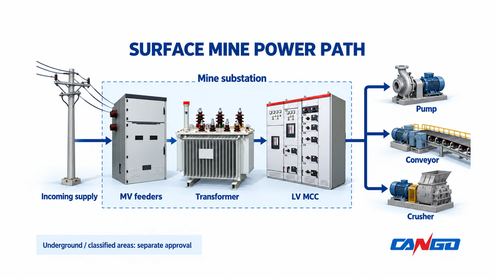
What mining power distribution must cover
“Mining” can describe several different electrical environments. An open-pit mine, a mineral-processing plant, a materials-handling system, a ventilation plant and an underground working may share an owner and a production plan while having different equipment, environmental and approval requirements.
This article addresses ordinary industrial distribution for surface mining and mineral-processing facilities. It does not establish suitability for an underground mine, an explosive atmosphere or any other classified location.
The equipment layers have different jobs:
| Layer | Primary function | Information that must be confirmed before selection |
|---|---|---|
| Incoming supply | Connect the mine system to the responsible utility or upstream network | Voltage, frequency, available fault level, supply reliability, metering, interface ownership and utility requirements |
| Mine substation | Receive, switch, transform and distribute power at the required system boundaries | Incoming and outgoing voltages, bus arrangement, transformer duty, switching/protection scheme, enclosure and environmental requirements |
| MV bus and feeders | Distribute medium-voltage power to process areas or local transformers | Network topology, feeder loading, fault duty, isolation, protection, cable route and outage consequence |
| Transformers | Change voltage for distribution or motor loads | kVA, voltage ratio, frequency, impedance, vector group, taps, losses, cooling, ambient and installation conditions |
| LV MCC and distribution | Split the LV supply, control motors and provide protection and isolation | Incoming duty, busbar rating, motor schedule, starter duty, feeder protection, control philosophy and maintenance access |
| Motors and driven equipment | Convert electrical power into pumping, conveying, crushing, grinding, ventilation or other process work | Motor rating, duty cycle, starting method, starting current, acceleration requirement, environment and criticality |
Mining systems can be energy-intensive and may include both extraction and processing loads. The U.S. Department of Energy’s Mining Industry Energy Bandwidth Study discusses energy use across mining stages, but its historical findings do not establish a present-day load profile, saving or equipment rating for a new project.
Start with the mine load schedule and operating zones
The load schedule is the common reference for the electrical design. A list of motor nameplate ratings is not enough. It should show where each load is located, when it operates, how it starts and what happens to production or safety if it stops.
At minimum, organize the schedule by operating zone and process function. Record the assigned supply voltage, rated input, power factor and efficiency basis, duty cycle, expected simultaneity, starting method and criticality. Include non-motor loads such as heaters, lighting, instrumentation and control systems where they affect the distribution scope.
Separate normal operation from starting and abnormal conditions
Motor starting can affect voltage, protection and upstream equipment. A large motor may have a modest running load but a much larger starting current. The project study needs to consider the motor, driven-equipment inertia, starting method, source strength, transformer impedance and the acceptable voltage condition at other connected loads.
This article does not prescribe a starting method or a voltage-dip limit. The responsible electrical engineer should define the study basis, applicable project criteria and the equipment or process limits that the starting event must respect.
Do the same for abnormal operation:
- Which loads must remain available during a source outage?
- Which process areas can be shed or restarted in sequence?
- Which motors must not be restarted together?
- Which feeders require isolation for maintenance?
- What spare capacity or future connection point is genuinely required?
The answers change the topology, protection and equipment scope. They should be documented before the single-line diagram is frozen.
Map physical and approval boundaries
Draw the mine layout, substation positions, cable routes, process areas, control locations and responsibility boundaries on the same planning set. Mark areas that require a different environmental or hazardous-location review.
Electrical safety in mining is not improved by applying a generic “mine-rated” label to ordinary equipment. NIOSH’s mining electrical-injury overview identifies electrical hazards as a mining safety concern. The exact regulatory regime, classification method and equipment evidence depend on the country, site and operating area.
Choose the feeder topology around outage requirements
Radial, loop and dual-source arrangements solve different operating problems. Their names do not prove redundancy, selectivity or safe transfer.
| Starting arrangement | Useful when | Questions to resolve |
|---|---|---|
| Radial feeder | Loads can accept the consequence of losing their single supply path, and a simpler isolation boundary fits the operating plan | What is lost on a feeder fault, how will the fault be located, and where is the isolation point? |
| Loop or ring arrangement | The network needs an alternative path or sectional isolation between nodes | Is the loop normally open or closed, how is the transfer controlled, and can every section carry the required post-transfer duty? |
| Dual-source or main-plus-alternate arrangement | The process needs a planned alternative source or a higher level of supply continuity | Are sources interlocked, is transfer manual or automatic, and what happens to motors and controls during transfer? |
| Hybrid arrangement | Different process areas have different criticality, density or expansion requirements | Which loads justify the extra switching boundary, and how will the system remain operable during maintenance? |
A loop on a drawing does not automatically deliver a redundant supply. The study must show the normal switching state, the fault response, the transfer procedure and the capacity available after a section is isolated.
Keep the physical topology aligned with the operating procedure. A network that is electrically possible but difficult to isolate, label or restore is a weak operating design.
Coordinate the mine substation, MV feeders and transformers
The incoming supply establishes the fault and voltage environment. The substation and MV feeders must be selected for that environment, while the transformer changes voltage for the downstream system. These are connected design choices.
Establish the single-line diagram and fault basis
The single-line diagram should identify every source, bus, incoming and outgoing way, transformer branch, LV interface and planned tie. Add the required isolation and earthing provisions.
Obtain the fault-study basis from the responsible network owner or project engineer. Do not infer a fault level from the apparent size of a cabinet. The required switching and protection duty must be checked against the actual system study and the offered equipment.
If the project uses MV switchgear, the equipment scope should be read against the applicable framework. IEC 62271-200:2021 covers AC metal-enclosed switchgear and controlgear above 1 kV and up to and including 52 kV within its published scope. That scope does not certify a particular mine installation or approve a CANGO assembly.
The MV switchgear quotation checklist and single-line diagram reading guide can help organize the next-level inputs.
Define transformer duty as part of the system
For each transformer, confirm the load it serves, the voltage ratio, frequency, rated capacity, impedance, vector group, tap arrangement, cooling mode and expected operating profile. Include the effect of harmonic-producing loads and motor starting where relevant.
The transformer is not selected from kVA alone. The transformer kVA sizing guide covers the wider load calculation, while the transformer impedance guide explains why impedance affects fault current and voltage behaviour. Both decisions belong in the same study as the upstream and downstream protection.
For power transformers within its published scope, IEC 60076-1:2011 provides the general requirements framework. It does not establish a project-specific rating, loss level, cooling performance or mine suitability.
Compare the offered substation boundary
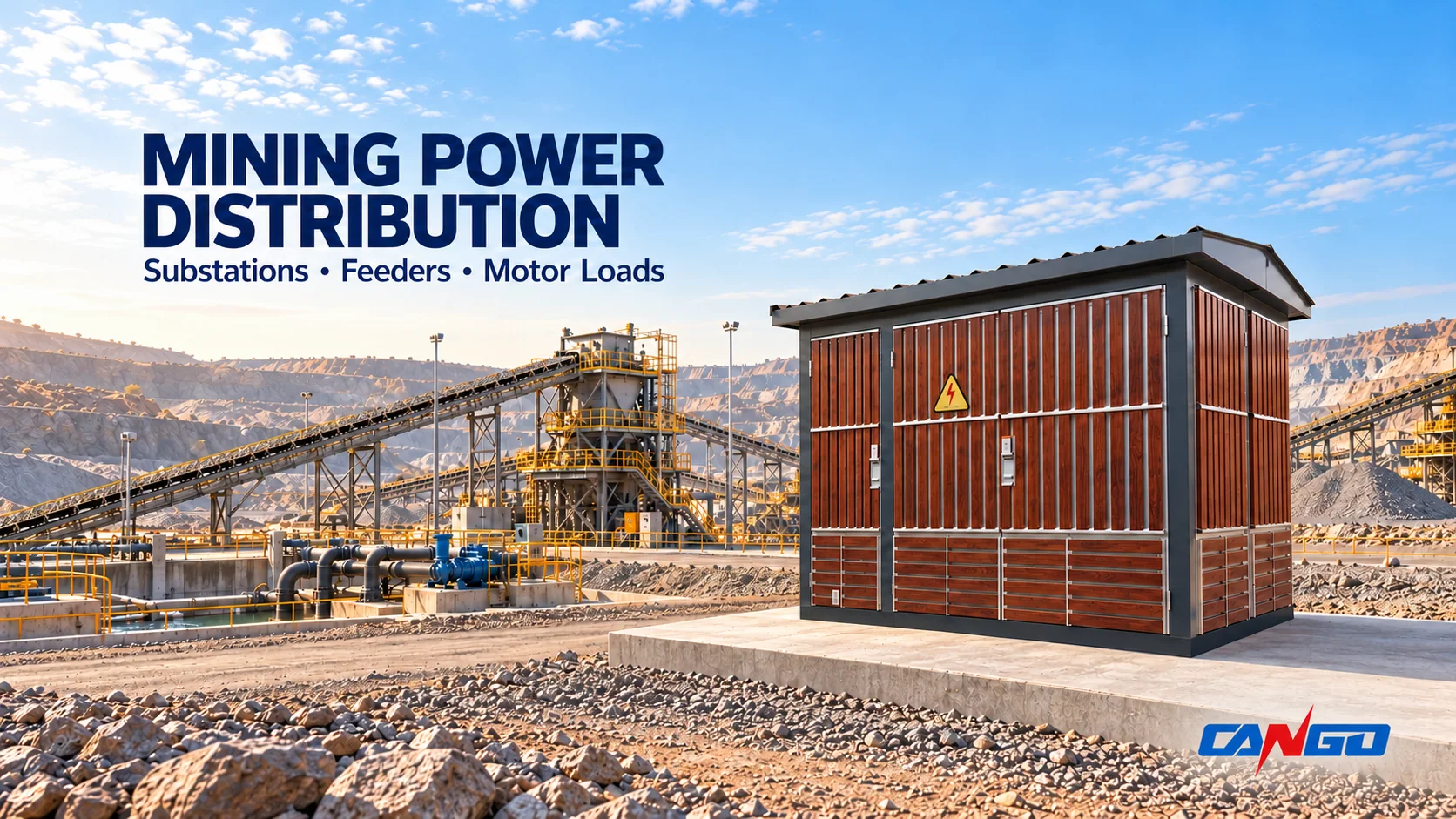
A “mine substation” may be a project function rather than one standard product. Depending on the site, it may contain separate MV switchgear, a transformer and LV distribution in an enclosure, a modular cabin, or another arrangement.
CANGO publishes the YB0-12/0.4 compact prefabricated substation for applications including industrial and mining projects and the 10kV–40.5kV modular prefabricated cabin for industrial and mining self-use substation applications. Those first-party descriptions provide starting points for an inquiry. Confirm the actual voltage, transformer, switching, LV feeder, enclosure and environmental scope for the project.
Define the LV MCC and motor-control boundary
The LV motor-control centre is where the motor schedule becomes an assembly. Its incoming section, busbar, outgoing feeders, starters, controls, metering and protection must match the transformers and the loads they serve.
Begin with the motor schedule and the required control philosophy. Identify which motors need direct-on-line, reduced-current, variable-speed or other starting arrangements only after the driven equipment and supply study establish the requirement. Confirm whether the starter is inside the MCC, at the motor or in a separate control panel.
Make the functional and physical boundaries explicit
The same MCC name can cover different arrangements. Define:
- The incoming device and busbar duty.
- The number and rating of outgoing feeders.
- The starter types and control interfaces.
- The fault level at the MCC location.
- The required isolation and earthing points.
- The fixed or withdrawable construction and the maintenance access it supports.
- The communication, metering and process-control interfaces.
The LV switchgear planning guide covers the wider assembly-planning inputs. The fixed versus withdrawable comparison helps separate construction preference from the actual operational requirement.
For LV power switchgear and controlgear assemblies, IEC 61439-2:2020 provides the Part 2 scope alongside the general rules of Part 1. It does not qualify a complete mine system or replace the project’s verification and acceptance process.
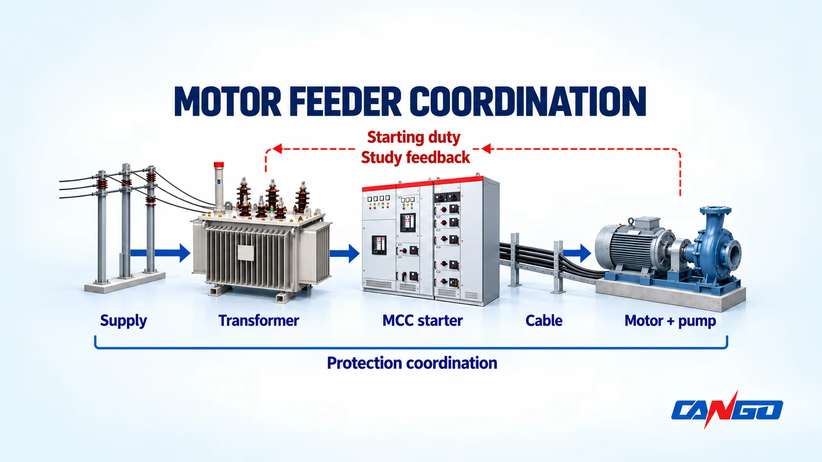
Coordinate the cable, starter and protection
For each motor feeder, carry the same duty through the cable, starter and protection:
| Input or check | Why it belongs to the feeder decision |
|---|---|
| Motor and driven-equipment duty | Determines the required starting and running performance, not just the nameplate current |
| Supply voltage and fault level | Establishes the available source and the fault duty at the MCC |
| Transformer characteristics | Affects voltage during starting and the fault current delivered downstream |
| Cable route and installation conditions | Influences the required conductor and installation method; the project engineer must verify these |
| Starter and control scheme | Defines the interface between the process control and the motor circuit |
| Protection and isolation | Must be coordinated with the upstream device and the operating procedure |
This is a coordination problem, not a collection of independent purchases. A larger transformer or a different starter may change one constraint while making another worse. Record the study basis and the final equipment interface in the project documents.
Treat earthing, overvoltage, cable routes and environment together
Electrical equipment is installed in a physical system. Earthing and bonding, surge protection, cable routing, enclosures, ventilation and maintenance access all affect whether the selected equipment can be operated as intended.
Earthing and bonding
Define the earthing system for sources, substation equipment, transformer neutrals where applicable, LV assemblies, motors and cable screens. Identify the responsibility boundary between the utility, the mine, the EPC contractor and the equipment supplier.
The equipment enclosure is not a substitute for a project earthing design. Earthing conductors, connections, fault paths and touch-voltage management require the project’s electrical study and the applicable installation requirements.
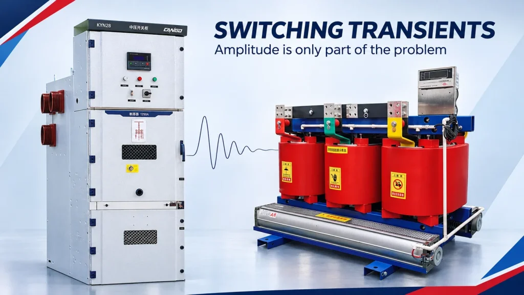
Overvoltage and switching
Confirm whether the incoming supply and outgoing feeders need surge protection, switching provisions or other overvoltage measures. The type and location depend on the system, exposure, cable route and protection philosophy.
Do not choose a device because it appears in a similar project. Start with the single-line diagram and the responsible engineer’s insulation-coordination and protection requirements.
Cable route and environmental conditions
The route can affect the cable, enclosure and maintenance arrangement. Record:
- Indoor, outdoor, covered or exposed installation.
- Ambient temperature, solar exposure and ventilation.
- Dust, moisture, condensation, corrosion and washdown.
- Cable entry direction, bending space and pulling route.
- Transport, lifting, foundation and future replacement.
- Required enclosure protection and the evidence offered for it.
An IP or enclosure rating must be read with its declared test and application conditions. Appearance alone does not establish dust, water or corrosion performance.
Keep hazardous-area equipment in a separate approval scope
Underground workings and classified locations need a separate engineering and approval process. The classification method, permitted equipment, marking and documentation depend on the jurisdiction and the actual area classification.
The following are not interchangeable:
- A conventional industrial cabinet with a robust enclosure.
- A product described as suitable for mining applications.
- Equipment approved for a particular hazardous location or explosive atmosphere.
CANGO’s conventional prefabricated substations, switchgear, transformers and distribution cabinets should not be treated as underground, explosion-protected or hazardous-area equipment unless a specific project offer is supported by the required classification, product evidence and approval.
The mine electrical system also needs an operating and maintenance boundary. Isolation, lockout, work permits, fault finding and testing must follow the owner’s procedures and applicable requirements. A manufacturer’s product description does not authorize work on energized equipment.
Build the mining RFQ around comparable boundaries
A useful RFQ allows suppliers to quote the same electrical function and the same site boundary. It should not rely on a model name or a single line item.
| RFQ section | Required project information | Why it prevents an incomplete offer |
|---|---|---|
| Project basis | Country, site environment, system frequency, applicable standards and approval requirements | Establishes the regulatory and environmental context |
| Single-line diagram | Sources, buses, transformer branches, ties, feeders, isolation and earthing provisions | Shows the electrical boundary to be supplied |
| Load schedule | Process areas, motor ratings, duty, starting, criticality and expected operation | Connects the equipment to the real load |
| Supply study | Voltage, fault level, supply reliability and utility interface | Establishes switching, fault and protection duty |
| Transformer schedule | kVA, voltage ratio, impedance, vector group, taps, cooling and losses | Allows transformer offers to be compared on the same duty |
| MV switchgear schedule | Ways, ratings, switching/protection devices, interlocks, metering and cable interfaces | Prevents an offer from omitting required functions |
| LV MCC schedule | Incomer, busbar, feeders, starters, controls, protection, metering and construction | Turns the motor schedule into an assessable assembly scope |
| Installation conditions | Indoor/outdoor, ambient, dust, moisture, altitude, corrosion, cable entry and transport | Keeps enclosure, cooling and layout assumptions visible |
| Scope split | Equipment, cables, foundations, earthing, installation, testing, commissioning and documentation | Exposes gaps that a low equipment price can hide |
| Verification | Required type/routine evidence, drawings, test records and approval documents | Makes the evidence obligation part of the offer |
For the wider substation inquiry, use the prefabricated-substation inquiry checklist. The power-transformer project-information guide covers transformer-specific inputs.
A conditional CANGO equipment starting point
Once the project boundaries are fixed, CANGO equipment can be reviewed against the relevant duty:
| Project need | CANGO starting route | Confirm before selection |
|---|---|---|
| Coordinated MV/transformer/LV distribution in a compact station | YB0-12/0.4 prefabricated substation | Voltage, transformer, MV scheme, LV feeders, enclosure, cooling and site conditions |
| Larger modular or prefabricated cabin arrangement | 10kV–40.5kV modular prefabricated cabin | Actual system voltage, layout, enclosure and project-specific equipment scope |
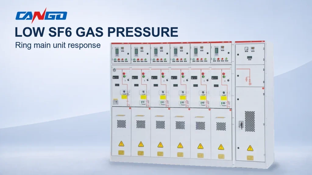
| Indoor medium-voltage distribution | KYN61-40.5 medium-voltage switchgear | System voltage, fault duty, switching/protection scheme and room arrangement |
| LV motor control or distribution | GCK or GCS low-voltage switchgear | Motor schedule, starter scope, fault level, busbar, feeder arrangement and maintenance plan |
| Fixed LV distribution | GGD or XL-21 cabinet | Actual voltage, feeder scheme, installation location and enclosure requirement |
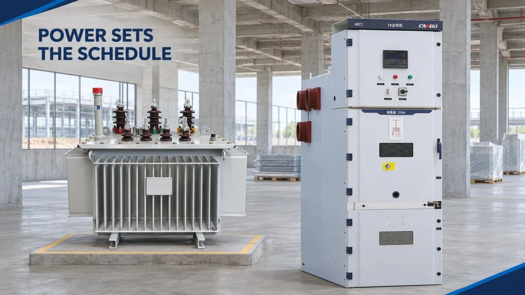
| Transformer for the downstream distribution boundary | Oil-immersed or dry-type transformer route | kVA, voltage ratio, impedance, vector group, cooling, losses, ambient and installation conditions |
These are conditional equipment routes, not a recommendation to combine every family into one system. The CANGO industrial power solution and product categories provide the broader navigation.
Send the mine layout, single-line diagram, load schedule, supply and fault study, transformer and switchgear schedules, MCC schedule, environmental conditions, hazardous-area boundary and required documentation together. Ask CANGO to review the equipment scope against those inputs.
The objective is not to receive the largest equipment list. It is to receive an offer whose boundaries, duties, interfaces and evidence can be compared.
References
- NIOSH/CDC — Electrical Injuries, mining electrical-safety overview.
- U.S. Department of Energy — Mining Industry Energy Bandwidth Study, historical energy study.
- IEC — IEC 62271-200:2021, AC metal-enclosed switchgear and controlgear, official scope summary.
- IEC — IEC 61439-2:2020, power switchgear and controlgear assemblies, official scope summary.
- IEC — IEC 60076-1:2011, power transformers, official scope summary.
- CANGO product information — YB0-12/0.4 compact prefabricated substation, 10kV–40.5kV modular prefabricated cabin, KYN61-40.5 medium-voltage switchgear, GCK low-voltage switchgear, GCS low-voltage switchgear, GGD low-voltage switchgear, XL-21 low-voltage distribution cabinet, S11-M oil-immersed transformer and SCB10 dry-type transformer, including their application statements.