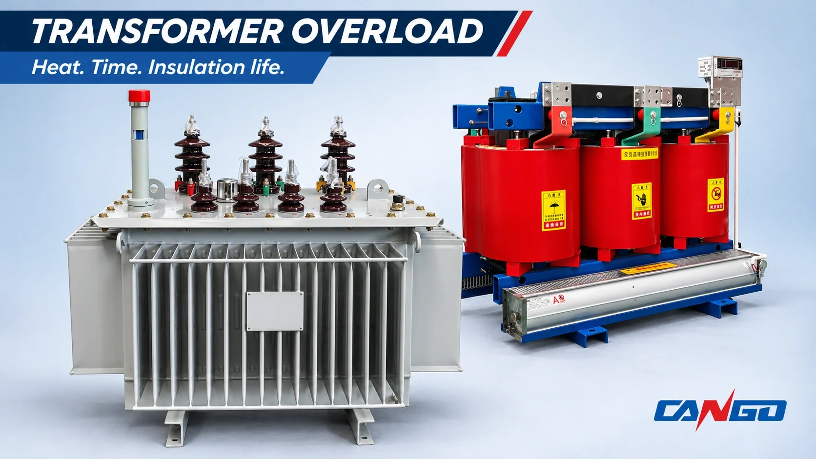
Short answer: Do not treat 125% of nameplate kVA as a continuous rating. A temporary peak may be assessed using the applicable loading guide only when its pre-load, ambient temperature, cooling condition and temperature history are known; insulation aging is part of that decision. Do not authorize overload as a workaround for continuous excess demand, excessive ambient temperature, poor ventilation or deteriorated insulation. Read the nameplate, establish temperature trends and obtain the manufacturer’s assessment using the checklist in Section 6.
1. Where the 125% myth comes from
The Mike Holt Forum question, “Can a Transformer Handle 125% of it’s rated KVA?”, captures a recurring misunderstanding: a question about a 112.5 kVA, 208 V three-phase transformer, described as rated at 312 A, asks whether it can be used at 390 A. Those figures describe the question being posed, not a verified operating case or a loading allowance.
The distinction is that 125% is not a continuous nameplate rating. A percentage associated with a protection discussion or a temporary-loading example cannot be transferred directly to continuous transformer output. Being able to energize the load without an immediate trip does not demonstrate acceptable winding temperature or insulation aging.
The forum question is used only to show the misconception. Neither replies nor any temporary-loading figures attributed there to NEMA establish this article’s technical basis. The loading discussion below uses IEC 60076-7 for mineral-oil-immersed equipment and IEC 60076-12 for dry-type equipment, with their different scopes and conditions kept separate.
The question’s US 208 V setting also does not describe CANGO’s 10 kV-class/0.4 kV product ratings. It is a prompt to investigate thermal capability, not a worked CANGO example. For an existing installation, the relevant starting point is its actual nameplate and operating history.
2. What “rated kVA” actually means
Rated kVA is a thermal capability under specified service and cooling conditions, not a universal reserve above the nameplate. The useful chain is load current → winding loss → temperature rise → winding hot spot → insulation aging. Increasing current raises resistive winding loss according to I²R; the resulting temperature depends on how the equipment stores and rejects that heat.
A measured current percentage is therefore only one input. A transformer entering a peak from a cool, lightly loaded condition is thermally different from the same transformer entering it after sustained heavy loading. A cool morning and a hot enclosure also represent different starting conditions even if the measured load is identical.
The temperature-rise designation and insulation system are related but are not interchangeable. Use Dry-Type Transformer Temperature Rise vs Insulation Class Explained for that distinction rather than treating an insulation-class label as permission to overload.
For oil-filled equipment, top-oil temperature describes the bulk cooling environment while the winding hot spot can be hotter and respond differently. A satisfactory-looking top-oil reading alone cannot establish the winding hot-spot condition. The loading assessment must connect the two through the applicable measured or validated thermal information.
The question is not simply “How far above rated current are we?” It is “Where will the hot spot go, for how long, and what will happen during recovery?” The cycle after the peak matters as well as the peak itself.
3. Oil-immersed vs dry-type: why overload behaves differently
Oil-immersed transformers
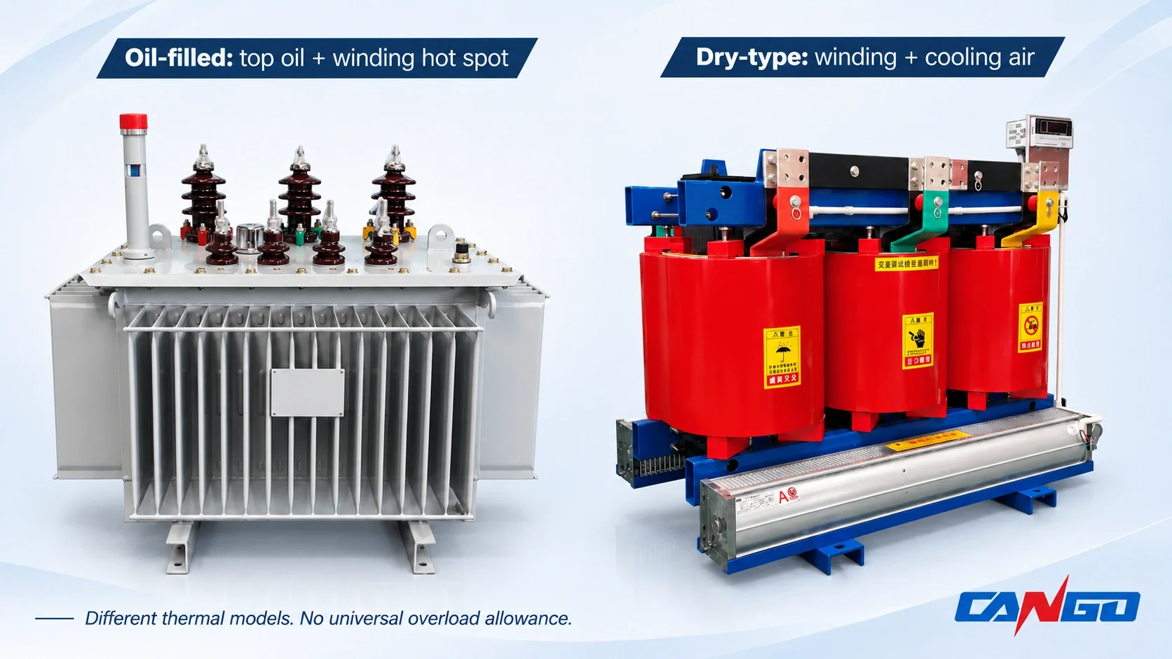
CANGO S11-M is an example of an oil-immersed family, not a blanket overload promise. Oil provides thermal storage and carries heat toward the tank’s cooling surfaces. Bulk-oil temperature can lag a load change; that lag is not proof that the winding has the same margin. A loading assessment considers both the oil behavior and the winding hot spot through the actual starting condition and peak.
Cooling stages matter only when they belong to the transformer’s documented design. An ONAN unit and equipment with a declared ONAF rating must be assessed under the relevant cooling stage. Fans can support a higher declared stage where provided, but adding airflow does not automatically create a new rating for an S11-M or any other installed transformer.
Oil condition also belongs in the pre-overload assessment. Review applicable moisture and dielectric-breakdown results against the manufacturer’s criteria and accepted history. A transformer with unresolved oil or insulation concerns should not gain an assumed temporary allowance merely because its load has previously been lower.
Dry-type transformers
For an SCB-family dry-type transformer, heat from the cast-resin winding assembly is rejected to air rather than buffered by an oil inventory. Winding temperature can respond more quickly, and air paths, inlet-air conditions and enclosure ventilation become especially important. Actual response still depends on the design and its thermal time constant; no universal oil-to-dry time ratio is implied.
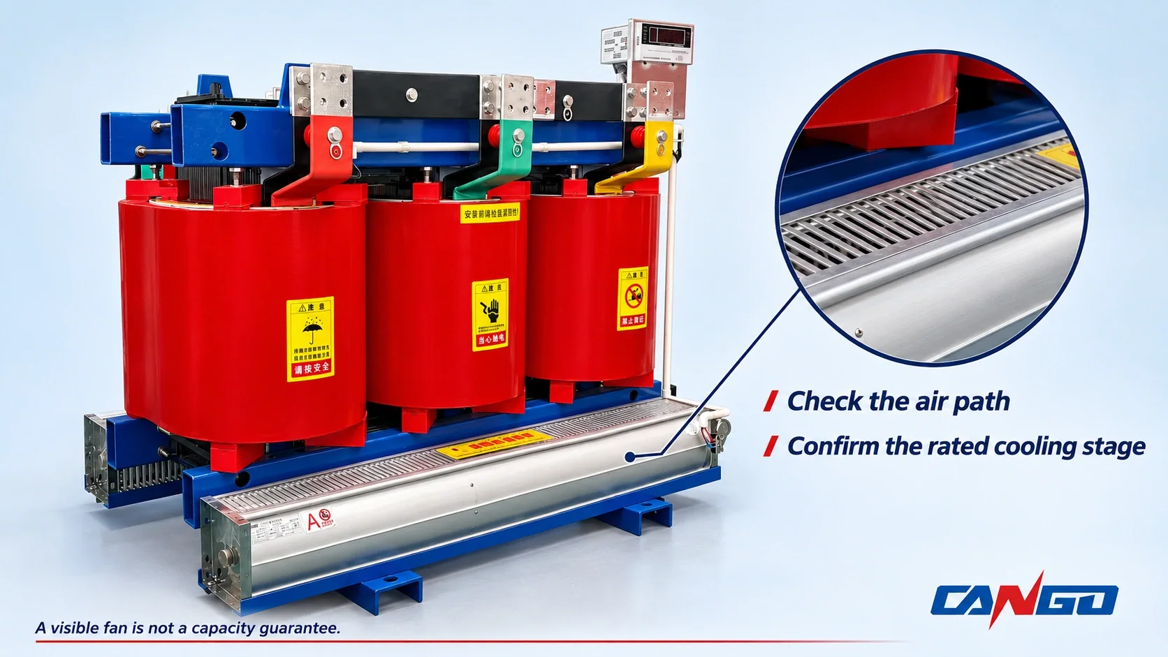
Check the actual insulation system and any declared natural/forced-air arrangement. A visible fan does not prove that a capacity increase is available, that it is operating correctly or that its rating matches the intended duty. Temperature-controller information also needs to be interpreted against the manufacturer’s sensor arrangement and instructions.
After moisture exposure, insulation resistance and evidence of damp contamination are important condition checks before proposing additional thermal stress. Use the actual acceptance criteria and baseline; a generic resistance number is not appropriate. Keep this construction distinction separate from the broader purchase comparison in Oil-Immersed vs Dry-Type Transformers.
| Comparison point | Oil-immersed | Dry-type |
|---|---|---|
| Cooling medium | Oil transfers heat to the tank/cooling surfaces and surrounding air | Winding assembly transfers heat to surrounding air through its designed passages |
| Key temperature points | Top oil and winding hot spot, evaluated together | Winding hot spot and actual cooling-air conditions |
| Heating response | Bulk-oil buffering and lag; winding response remains important | Often more responsive to load and ventilation changes; model-specific time constant |
| Essential pre-overload checks | Applicable oil/insulation condition, cooling stage and temperature history | Winding/insulation condition, moisture history, ventilation and declared cooling arrangement |
4. How much overload, and for how long?
There is no unconditional multiplier-to-duration table. The following is a conditional assessment table, not an authorization to operate above nameplate. Numerical duty/time pairs are deliberately omitted because they cannot be selected without the applicable design, insulation system, initial temperature and operating assumptions.
| Overload level | Duration | Pre-load before overload | Ambient condition | Cooling type (oil / dry) | What the loading guide says | Source |
|---|---|---|---|---|---|---|
| Proposed peak from the measured load curve; no generic multiplier | Determine for the complete cyclic duty | Record the preceding load history and starting oil/winding thermal state | Use the actual ambient profile, not an unspecified room temperature | Oil: declared operating stage | Assess temperature and thermal aging across the load cycle using the applicable model; request manufacturer loading assessment | IEC 60076-7 |
| Proposed emergency duty; no assumed reserve | Determine for the actual emergency and recovery period | Establish the real starting load and temperatures; do not assume a cool transformer | Include the expected ambient during the event | Oil: available, documented cooling stage | Emergency-duty assessment has conditions and limitations; it is not a new continuous rating | IEC 60076-7 |
| Proposed transient peak; no generic multiplier | Determine from winding-temperature response | Record preceding load and initial winding condition | Establish actual inlet-air/ambient conditions and enclosure effect | Dry: specified natural or forced-air arrangement | Assess hot-spot response and insulation lifetime consumption using the dry-type model and actual construction | IEC 60076-12 |
| Repeated or prolonged above-nameplate duty | Assess the repeated cycle; do not assign an automatic hour allowance | Include accumulated heating before every peak | Include sustained high ambient and restricted-air conditions | Dry: verified operating cooling arrangement | Evaluate consequences and limitations with the manufacturer; recurring excess duty can require added capacity | IEC 60076-12 |
Do not mix tables from different standards, insulation systems or pre-load assumptions. Conflicting vendor-blog claims such as 125%, 150% or 200% do not establish comparable capabilities when their conditions differ or are missing. None of those vendor duration figures is adopted here.
For a usable answer, submit the peak, duration, pre-load, ambient history, cooling stage and temperature information together. Ask for the permitted duty, its applicable limits and the recovery requirement in writing. A single acceptable operating point does not establish the next day’s allowance if the starting condition changes.
5. What overload costs you
Insulation life
Higher hot-spot temperature can accelerate thermal aging. The loading guides assess that effect over time and over the relevant load cycle; a peak percentage alone cannot produce a credible life-cost estimate. Cooler periods can affect the cycle’s aging assessment, but do not erase damage or justify borrowing an allowance from an unrelated example.
No universal “life halves” rule, loss-of-life percentage or remaining-life guarantee is given here. Insulation condition and the applicable model matter, and the absence of an immediate failure is not evidence that no aging has occurred. The manufacturer should explain the assumptions behind any life-consumption estimate.
Losses and operating cost
At comparable winding resistance, resistive load loss rises with current squared. Temperature-related resistance changes and other loss components complicate the actual operating result. Additional losses consume energy and add heat, so a temporary capacity solution also has an operating-cost consequence; it is not free output above the nameplate.
Do not infer a universal efficiency penalty or electricity bill from that relationship. Use measured loading, applicable loss data and the actual operating period. Distribution Transformer Losses: No-Load vs Load Losses separates the loss components without turning one into a loading permission.
Protection and short-circuit implications
Overload is increased operating load, not a change to the transformer’s nameplate impedance or an automatic increase in prospective short-circuit current. Replacing it with a larger unit or adding parallel capacity can change available fault duty and protection coordination. The actual network calculation must be reviewed rather than inferred from the new kVA alone.
Check overload and temperature protection against the proposed loading plan without defeating protective functions. For the separate fault-duty relationship, see Transformer Impedance and Short-Circuit Current.
Oil-specific risks
Excess thermal stress can accelerate deterioration of the oil/solid-insulation system and contribute to gas formation. Review dissolved-gas-analysis trends as condition-monitoring evidence alongside temperature and loading history. A trend needs competent interpretation; one oil reading does not authorize overload or establish the absence of internal deterioration. This article does not provide a DGA diagnostic table or ratio method.
6. The 7-step check before you overload
The output should be a bounded operating proposal with an owner, stop conditions and a recovery plan. Qualified personnel must follow the site’s safety procedures for measurements, access and tests; this checklist is not an instruction to open or work on energized equipment.
- Read the nameplate and supporting documents. Establish rated capacity, cooling arrangement, insulation system, temperature-rise designation, impedance and vector group. Pass: the actual unit and applicable loading basis are identified. Stop: a critical rating is unknown, ambiguous or borrowed from another model.
- Record the load curve. Establish the peak, its duration, pre-load and the expected recovery loading. Pass: the proposed duty can be represented as a documented cycle. Stop: only a maximum current or an assumed starting load is available.
- Establish temperature trends. Record ambient and the relevant winding/top-oil information continuously across the duty using approved installed measurements or a validated model. Pass: the thermal starting point and predicted response can be assessed against applicable limits. Stop: only a spot reading exists, a sensor is unreliable or a required thermal limit is unconfirmed.
- Verify cooling and ventilation. Confirm available fans, control functions and unobstructed heat-rejection paths against the actual declared cooling arrangement. Pass: the assessed cooling stage is available throughout the proposal. Stop: cooling is impaired or capacity depends on an undocumented fan uplift.
- Check condition for the construction. For oil-filled units, review the applicable oil tests and DGA trends; for dry-type units, review insulation resistance and moisture/contamination evidence. Pass: findings satisfy the manufacturer’s assessment and accepted condition history. Stop: abnormal or unresolved results undermine the proposed thermal duty.
- Review protection. Check overload and temperature-protection settings against the operating proposal and approved coordination. Pass: the duty and protection are compatible without suppressing required protection. Stop: the proposal depends on ignoring alarms, disabling trips or unsupported setting changes.
- Obtain manufacturer review. Submit the complete evidence package. Pass: the duty is within a confirmed applicable loading assessment; operation outside the nameplate or guide’s applicable scope requires written manufacturer advice and responsible engineering approval. Stop: the assessment, limits or written opinion required for the proposed operation is missing. This article supplies no such approval.
7. When NOT to overload – upsize instead
Do not authorize the proposed overload when any of these conditions is unresolved:
- Continuous demand already exceeds 100% of the applicable rating.
- Ambient temperature remains above the declared service conditions.
- Ventilation is restricted or the available cooling stage is already fully used.
- Insulation condition is deteriorated or relevant oil results are abnormal.
- Critical loads have no suitable reserve or contingency for the proposed risk.
- The proposal must continue as a long-term workaround rather than a bounded peak.
Move to load reduction, additional capacity or a suitably rated replacement rather than trying to extend an unsupported allowance. Return to How to Size a Distribution Transformer in kVA when the existing thermal envelope cannot serve the requirement. Parallel expansion also needs compatibility review; Dyn11 vs Yyn0 Transformer Vector Groups provides the related connection context.
8. CANGO ranges this applies to
CANGO’s dry-type pages cover SCB10, SCB12, SCB14-NX2, SCB18-NX1 and SCBH15 amorphous-alloy equipment in the 10 kV class, with published 0.4 kV low-voltage options, Dyn11/Yyn0 connection options and listed capacities reaching 2500 kVA by model. Tap details vary: the pages show ±2.5%/±5% arrangements and selected capacities with ±2×2.5%/±5%. Confirm the exact ordered configuration rather than applying one tap schedule across the family.
Use SCB12 vs SCB14 vs SCB18 Dry-Type Transformers for the product comparison. For SCBH15’s material context, see Amorphous Alloy vs Silicon Steel Transformers; a different core material does not establish an overload guarantee.
The S11-M oil-immersed page lists the 10 kV class, 0.4 kV low voltage, Dyn11/Yzn11/Yyn0 options and ±2×2.5%/±5% taps. Insulation, temperature rise, cooling arrangement and loading assessment remain model-specific and subject to the supplied documents. Final configuration is confirmed against project requirements before quotation.
FAQ
Can a distribution transformer run at 125% of its rated kVA?
Not as a continuous rating merely because that percentage is quoted. A temporary duty needs an applicable loading assessment using pre-load, duration, ambient temperature, cooling and winding-temperature behavior. The relevant oil-filled or dry-type loading guide must match the actual construction and insulation system. Do not assume that protection permitting current flow establishes thermal acceptability. If the evidence or necessary manufacturer advice is missing, reduce the load or review additional capacity instead.
How long can a transformer be overloaded?
It depends on overload level, duration, pre-load, ambient temperature and cooling arrangement. Establish those inputs and the initial thermal state, then use the applicable loading-guide method with the manufacturer’s data to determine an acceptable duty and recovery requirement. A generic number of hours cannot replace that assessment. Repeated peaks also need the complete cycle reviewed because the transformer may enter each peak hotter than it did previously. No unconditional duration table applies across all designs.
Is overloading a dry-type transformer different from overloading an oil-filled transformer?
Yes. An oil-filled assessment relates top-oil and winding hot-spot behavior, while a dry-type assessment considers winding temperature and its actual cooling-air arrangement without an oil reservoir. Thermal response, insulation system and ventilation therefore need different inputs and models. Use IEC 60076-7 for the applicable mineral-oil construction and IEC 60076-12 for dry type. Neither a fan nor a familiar product-family name proves the amount or duration of additional loading available.
Does overloading a transformer shorten its life?
Higher hot-spot temperature can accelerate insulation aging, and the duration and complete thermal cycle determine the assessed life consumption. The result cannot be inferred from the peak percentage alone. Initial condition, insulation system, cooling and subsequent recovery matter. A brief peak and sustained excess loading are different duties, but neither should receive a guessed life-loss figure. Request the applicable loading assessment and its assumptions rather than relying on a universal life-halving rule.
When should you replace a transformer instead of overloading it?
Consider additional capacity or replacement when continuous demand exceeds the applicable rating, ambient or cooling conditions leave no justified margin, insulation or oil condition is unsatisfactory, or the proposed overload becomes a long-term operating plan. Critical-load contingency also matters. First establish whether load reduction or rescheduling can resolve the constraint, then review the capacity solution and protection implications. Do not select replacement from one peak reading or assume a larger unit avoids all engineering checks.
References
- IEC, IEC 60076-7:2018, Loading guide for mineral-oil-immersed power transformers; official description and authorized preview. Used for conditional loading and thermal-aging principles, not a reproduced numerical loading table.
- IEC, IEC 60076-12:2008, Loading guide for dry-type power transformers; official description and authorized preview. Used for dry-type hot-spot, time and insulation-lifetime assessment principles.
- CANGO product information: SCB10, SCB12, SCB14-NX2, SCB18-NX1, SCBH15 and S11-M. Published product ranges are not an above-nameplate loading guarantee.