Water and wastewater power distribution should start with the service the plant must maintain during an electrical failure. Map the required pumps, blowers, treatment equipment and controls to their supply paths, then specify the intake, transformers, low-voltage boards, motor control centers (MCCs) and backup arrangements around those duties.
A standby pump does not provide independent service if it shares the failed feeder or MCC bus with the duty pump. Similarly, a generator can restore motor power while an unprotected controller loses its operating state during the transfer. Those dependencies matter as much as total installed motor power.
For project engineers and buyers, the useful starting document is a process-linked load schedule supported by an operating-state diagram. It should show what runs normally, what must survive a supply interruption, and what remains available during maintenance.
Establish the supply-to-process architecture
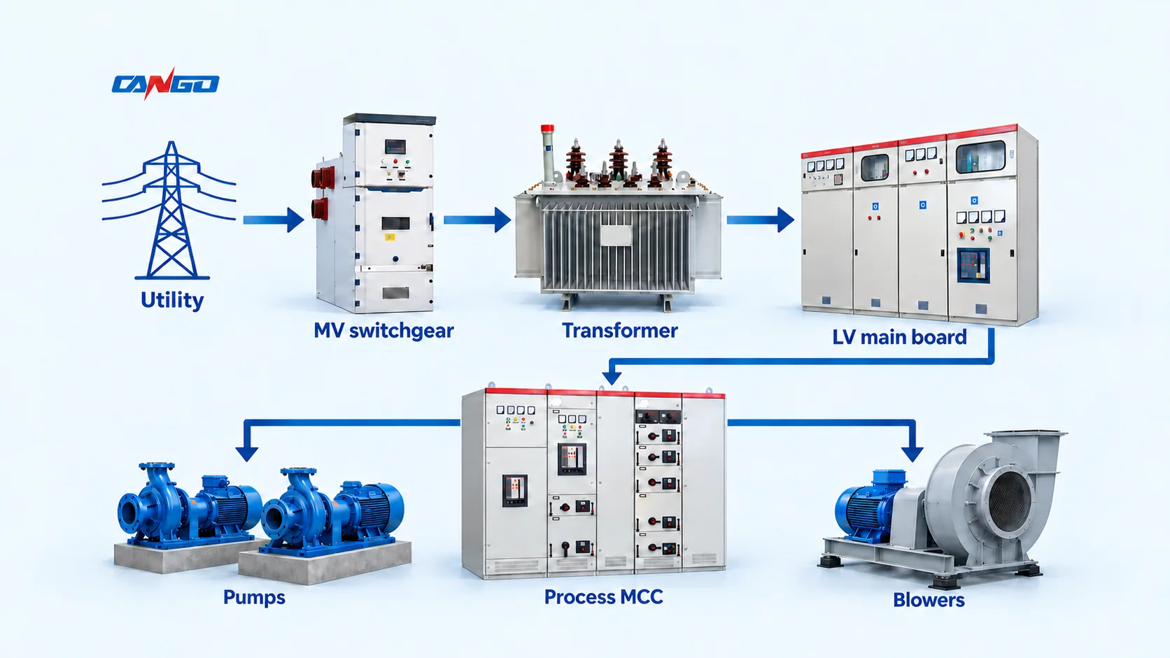
A plant taking a medium-voltage (MV) supply may use this functional chain:
Utility intake → MV switchgear → distribution transformer → low-voltage main board → process MCCs → motor feeders.
A smaller plant or remote pumping station may receive low voltage directly and omit the MV stage. Large motors may also have dedicated MV feeders. Select the arrangement from the utility connection, load locations and process requirements rather than treating one chain as mandatory.
The main board distributes power between process areas and auxiliary services. Each MCC groups motor switching, protection and control functions for its assigned loads. Local isolation, instrumentation and process interlocks complete the equipment interfaces.
Keep three boundaries visible on the single-line diagram:
- Supply boundary: which transformer, board section and incoming source feed each process group?
- Protection boundary: which device should isolate a feeder fault, and which other processes could lose power?
- Operating boundary: which circuits can be isolated for maintenance while the required water or treatment service continues?
These questions make the general industrial power-distribution arrangement specific to a treatment plant.
Build the load schedule around treatment duty
Drinking-water and wastewater plants share motor loads, but the consequences of losing them differ. A clear-water storage volume, wet-well operating range or process holding capacity may provide time to respond. That time must be established by the process team.
Use the following matrix to connect each equipment group to its electrical specification. The criticality and restart decisions are project inputs, not universal classifications.
| Process group | Typical electrical loads | Operating question | Input needed for the MCC or board |
|---|---|---|---|
| Drinking-water intake and delivery | Intake, transfer and high-service pumps | What flow or pressure must remain available after a failure? | Duty/standby combinations, motor data, starting method and pressure-control sequence |
| Filtration and backwash | Backwash pumps, air-scour blowers and valves | Can backwash be deferred, and which combinations run together? | Concurrent-load cases and valve/pump permissives |
| Wastewater collection and inlet works | Lift pumps, screens and grit equipment | How long before storage is exhausted or overflow becomes possible? | Wet-well limits, required pumping capacity and high-level alarms |
| Biological treatment | Aeration blowers, mixers and recycle pumps | What reduced treatment mode is acceptable, and for how long? | Minimum process duty, allowable interruption and restart dependencies |
| Disinfection and chemical dosing | Dosing pumps, ultraviolet (UV) equipment or associated auxiliaries | Which treatment functions must operate whenever water flows? | Flow interlocks, equipment demand and controlled stop/restart requirements |
| Sludge and site services | Sludge pumps, dewatering, ventilation and building loads | Which loads may be deferred without disabling essential equipment? | Load-shedding priority, ventilation dependencies and auxiliary demand |
For every motor, distinguish installed capacity, normal simultaneous operation and emergency operation. Do not apply a diversity factor that removes a process combination the plant actually needs. Conversely, counting every standby motor as continuously running can distort the demand assessment.
The US Environmental Protection Agency (EPA) power-resilience guide recommends a facility power assessment that identifies the equipment needed to maintain essential services. Its assessment approach is useful internationally, although it is US guidance rather than a substitute for local electrical or treatment requirements. See Power Resilience Guide, Section 2.
Check normal, outage and maintenance states
Pump redundancy and electrical redundancy are separate questions. If two pumps use separate outgoing starters but share one bus section, they remain exposed to that bus section being unavailable. Two incoming cables also need their upstream sources checked before they are described as independent.
Review the proposed architecture against at least these states:
| State | Question to resolve | Required evidence or decision |
|---|---|---|
| Normal operation | Can the required process combination run with planned auxiliaries? | Demand case, feeder schedule and thermal assessment |
| Utility loss | Which process group is restored, and which loads remain disconnected? | Essential-load schedule, transfer philosophy and restart sequence |
| One motor feeder unavailable | Can the standby machine maintain the required duty? | Separate supply path where required, available capacity and control logic |
| MCC bus or transformer unavailable | Which duty and standby machines are lost together? | Common-mode failure review and an accepted reduced-service arrangement |
| Planned isolation | Can personnel isolate the required work area without losing essential treatment? | Maintenance boundary, approved isolation arrangements and operating plan |
A bus tie or second transformer may change these answers, but it also changes fault levels, interlocks and operating rules. Define the permitted switching states before comparing cabinet prices. A spare drawer can support a maintenance strategy, but it cannot make an unavailable common bus healthy.
For the separate cabinet-construction decision, see fixed versus withdrawable low-voltage switchgear. The water-plant requirement is the service that must remain available while a particular feeder, compartment or board section is isolated.
Specify motor control and VFD interfaces
Choose direct starting, a soft starter or a variable-frequency drive (VFD) from the motor and process duty. A VFD is particularly relevant when the process needs variable flow, pressure or airflow. It is not an automatic energy-saving solution for every pump.
The US Department of Energy (DOE) explains that speed reduction needs careful assessment where static head is significant, and that pumps have minimum-flow operating limits. Match the proposed speed range to the pump and system curves before specifying the drive. See the pumping-system sourcebook, especially the adjustable-speed-drive discussion.
For the electrical package, resolve four interfaces:
Motor and process: provide rated current, starting and acceleration requirements, permitted starts, speed range, duty cycle and required protection signals. State whether a bypass is needed and whether full-speed bypass operation is acceptable to the process.
Drive and motor cable: give the route length, motor insulation information and drive requirements. Output-side voltage stress and bearing effects require coordinated drive, cable and motor selection. DOE Motor Systems Tip Sheet 15 discusses these interactions; it does not provide a universal filter or cable-length rule for every installation.
Drive and supply: obtain drive input-current data and assess the combined nonlinear load under utility and generator operation. Natural Resources Canada identifies distribution-system harmonics as a VFD application consideration in its VFD guide. Use a project power-quality assessment to determine mitigation and the applicable acceptance point. Do not assign a universal current-distortion limit at every drive terminal.
Drive and enclosure: include drive losses, adjacent loaded compartments, ventilation and room cooling in the thermal assessment. A nominally adequate starter compartment is not automatically suitable for a heat-producing drive. Any proposed power-factor correction or filtering should be assessed with the drive system; SVG and APF perform different functions.
Separate generator recovery from UPS ride-through
Standby generation and control ride-through solve different continuity problems. A generator supplies the selected emergency operating load after the transfer system accepts it. A suitably selected uninterruptible power supply (UPS) maintains its connected loads through the interruption within its declared performance and stored-energy limits.
The EPA guide discusses both motor starting and transfer arrangements in Section 3. The official scope of IEC 62040-3:2021 identifies continuity of load power as a primary UPS function. Neither source establishes a particular plant runtime or generator rating.
In one possible arrangement, the utility and generator are alternative inputs to an automatic transfer switch (ATS). Its selected output supplies an essential MCC and a separate UPS branch for the programmable logic controller (PLC), supervisory control and data acquisition (SCADA) equipment and specified field devices. The UPS branch does not carry the pump and blower motor load in this example.
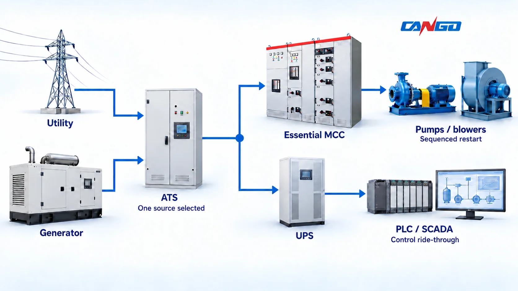
Define these duties separately:
| Duty | Specification input |
|---|---|
| Restore essential motor power | Running demand, motor-start steps, allowed voltage/frequency variation and loads to shed |
| Maintain control power | Actual UPS-connected loads, required autonomy, output compatibility and maintenance/bypass behavior |
| Keep useful process information | Power for the PLC, required field instruments and communications equipment, not only the operator screen |
| Restart safely | Valid level, flow, pressure, valve position and equipment permissives, plus the response to missing signals |
A practical restart plan first establishes a stable source and valid control information, then releases required motor loads in an agreed sequence. It must also define what stays inhibited after a protective trip or an unsafe process condition. The owner and process engineer set that sequence; there is no universal delay that suits every wet well, blower or treatment train.
Compare the generator against the actual starting steps, not only the sum of running kilowatts. Include UPS recharge and essential cooling or ventilation where applicable. The transfer design must prevent unintended source interconnection and utility backfeed; earthing, neutral treatment and protection require project-specific review.
Locate equipment for moisture, corrosion and flooding
An indoor electrical room beside a wet process area still needs an environmental specification. Record temperature, condensation risk, washdown exposure, dust, salt and corrosive gases. State where ventilation air comes from and whether the room remains suitable when cooling or ventilation is unavailable.
Wastewater corrosion deserves separate attention. The EPA report Hydrogen Sulfide Corrosion in Wastewater Collection and Treatment Systems, Sections 1.3–1.4 describes vulnerability of electrical contacts, controls and instrumentation. Review the actual atmosphere and material protection; an enclosure ingress-protection number alone does not establish suitability for that atmosphere.
Flood exposure is another location decision. Consider the whole essential path: board, MCC, generator connection, controls, cables and access. The EPA flood-resilience guide includes relocation or elevation of vulnerable controls and electrical equipment among its mitigation options. Set levels from the site’s flood assessment rather than copying a generic cabinet-plinth height.
Where a gas assessment identifies a hazardous classified location, ordinary-location cabinet selection is insufficient. Classification and equipment approval require their own review. For example, US OSHA 1910.307 treats classification area by area. The CANGO catalogue routes below are ordinary distribution-equipment starting points, not evidence of hazardous-location approval.
Turn operating requirements into assembly evidence
An MCC model name does not establish the performance of a proposed assembly. For an IEC-based specification, IEC 61439-1:2020 provides general rules and is used with the relevant assembly part. IEC 61439-2:2020 addresses power switchgear and controlgear assemblies. Confirm the contract edition and local adoption.
Ask the supplier to address the actual loaded arrangement, installed components and service conditions. Drive heat, ambient conditions, enclosure arrangements and feeder grouping must agree with the offered design. Component certificates alone do not settle assembly verification. The distinction between design and routine verification should remain clear in the document schedule.
The project review should also address fault current and protection under every permitted source state. A utility-fed fault case and a generator-fed case can produce different protection behavior. Define the required selectivity, motor starting allowances and earth-fault protection from the system study rather than reusing one set of settings without checking it.
Separate factory checks from site acceptance. The latter needs to demonstrate agreed transfer behavior, load shedding, process permissives, communication-loss responses and the approved restart sequence. Witnessing one motor start does not prove the whole treatment plant can recover from a source loss.
Prepare a CANGO equipment inquiry
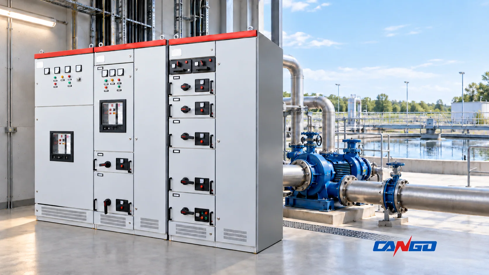
CANGO lists GCS withdrawable switchgear for distribution and centralized motor control, GCK MCC switchgear with power and motor-control arrangements, and GGD fixed switchgear for low-voltage distribution and control. These product families provide starting routes for an equipment discussion. Confirm the offered configuration, environment and project evidence before accepting suitability.
Send a coordinated inquiry rather than only a cabinet model and total motor kilowatts:
- System basis: single-line diagram, utility connection, transformers, permitted tie states, voltage/frequency and earthing arrangement.
- Process duty: required normal and emergency operation, allowable interruption, duty/standby groups and deferred loads.
- Motor schedule: rated data, starting method, VFD scope, bypass requirements, cable lengths and control interfaces.
- Continuity plan: essential-load schedule, generator interface, UPS-supported controls and restart permissives.
- Site conditions: room layout, access and isolation needs, cooling, corrosive exposure, flood assessment and any classified-area boundaries.
- Acceptance requirements: applicable standards, fault/protection studies, assembly documents, factory checks and site functional tests.
Use this package to review the relevant CANGO low-voltage switchgear and request configuration support. Identify separately who supplies and integrates the drives, generator, transfer equipment, UPS and process controls so the interfaces are included in the project scope.
References
- US Environmental Protection Agency. Power Resilience Guide for Water and Wastewater Utilities, updated May 2023; Sections 2–3.
- US Department of Energy and Hydraulic Institute. Improving Pumping System Performance: A Sourcebook for Industry, second edition, May 2006; pumping duty and adjustable-speed control.
- US Department of Energy. Minimize Adverse Motor and Adjustable Speed Drive Interactions, Motor Systems Tip Sheet 15, 2012.
- Natural Resources Canada. Variable Frequency Drives, public application guide; electrical considerations and harmonics.
- International Electrotechnical Commission. IEC 62040-3:2021 — Uninterruptible power systems: performance and test requirements, official scope summary.
- US Environmental Protection Agency. Hydrogen Sulfide Corrosion in Wastewater Collection and Treatment Systems: Report to Congress, May 1991; Sections 1.3–1.4.
- US Environmental Protection Agency. Flood Resilience: A Basic Guide for Water and Wastewater Utilities, September 2014; electrical controls, pumping and lift-station mitigation.
- US Occupational Safety and Health Administration. 29 CFR 1910.307 — Hazardous (classified) locations, US regulatory scope and location classification.
- International Electrotechnical Commission. IEC 61439-1:2020 — General rules and IEC 61439-2:2020 — Power switchgear and controlgear assemblies, official scope summaries.
- CANGO Power. GCS, GCK and GGD product information, checked October 26, 2026; first-party catalogue descriptions, not independent project qualification.