Current transformer selection for medium-voltage switchgear starts with the primary circuit, the receiving device and the complete secondary loop. Select the ratio for the operating range, allocate metering and protection duties, calculate external burden, then verify fault performance, insulation and physical fit. A ratio and a VA rating alone leave the specification incomplete.
The deliverable should be a CT schedule with a separate specification for each core, linked to the panel drawings and protection study. This guide covers conventional inductive current transformers with 1 A or 5 A secondaries. Low-power sensors, Rogowski coils and digital measurement interfaces require a different interface review.
Three checks deserve attention before a purchase order:
- A larger primary ratio changes both low-load measurement and the secondary current available to a relay.
- A lower installed burden helps reduce the required secondary voltage, but metering accuracy still needs a declared operating burden range.
- Fault-current withstand and accurate reproduction of fault current are separate requirements.
Start with the feeder duty and receiving devices
Use the feeder operating conditions and protection scheme to define the CT. The switchgear busbar current is useful panel information, but it does not establish the correct ratio for every outgoing circuit.
| Information to establish | What it determines |
|---|---|
| Minimum, normal and maximum operating current; expected expansion and overload duty | Candidate primary ratio, continuous thermal duty and measurement range |
| Meter and relay models, input ratings and functions | Secondary current, core allocation and required accuracy |
| Secondary wiring arrangement, route, conductor size and temperature | Installed external burden |
| Maximum and minimum fault currents, clearing times and system reactance-to-resistance ratio (X/R) | Accuracy during faults, transient assessment and withstand duty |
| System voltage, insulation coordination, frequency, ambient conditions and altitude | Electrical and environmental suitability |
| Primary conductor dimensions, CT location, compartment and access | Mechanical fit, insulation arrangement and service interfaces |
For an IEC-based project, identify the standards and editions in the contract. IEC 61869-2:2012 covers inductive CTs for measuring and protective devices at rated frequencies from 15 Hz to 100 Hz. Its published text references IEC 61869-1:2007. The newer general-requirements edition is IEC 61869-1:2023; agree the applicable combination and national adoption rather than silently replacing a dated reference. These publication details do not establish compliance of a particular CT or switchgear assembly. IEC Part 2, IEC Part 1.
If the complete panel specification is still being developed, first align it with the MV switchgear types and ratings. The CT review then resolves the measurement and protection interfaces within that equipment choice.
Allocate metering and protection cores separately
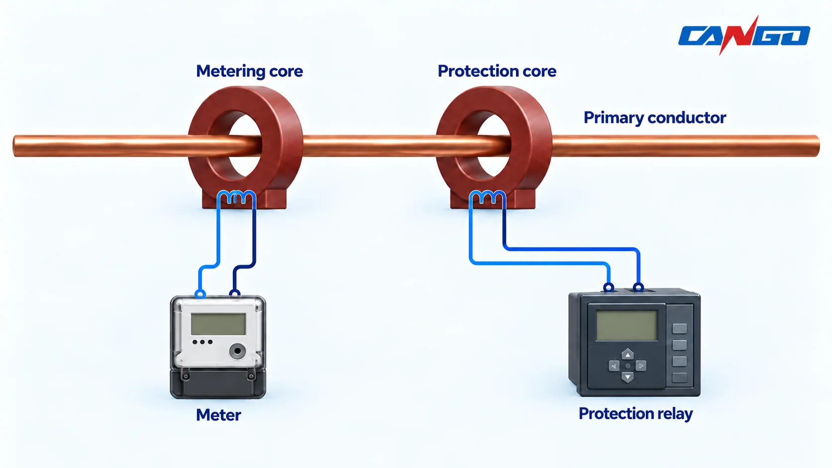
A meter needs useful accuracy across its operating current range. A protection relay needs a sufficiently faithful signal during the faults and operating conditions covered by its scheme. Those objectives can require different core characteristics. NPTEL’s CT equivalent-circuit discussion explains why both performance and saturation depend on the connected secondary impedance. NPTEL: metering and protection duties.
| Core duty | Specify and verify | Avoid assuming |
|---|---|---|
| Operational metering | Accuracy class, required current range, burden range and receiving-device input | A protection class also establishes low-current metering accuracy |
| Revenue or settlement metering | Metering authority requirements, approved configuration and accuracy evidence | A generally suitable CT is automatically accepted for billing |
| Feeder protection | Relay functions, class, rated burden and accuracy limit factor where applicable | The same class label suits every protection scheme |
| Differential or other demanding protection | Scheme-specific excitation, winding-resistance, matching and transient requirements | An ordinary feeder-protection core is automatically sufficient |
For metering cores, include the instrument security factor (FS) where required and check the receiver’s overcurrent withstand. FS concerns specified overcurrent behaviour; it should not be treated as a fixed secondary-current clamp. For class-P protection, state the accuracy class, rated burden and accuracy limit factor (ALF) together. BEST’s system-protection manual illustrates these as separate specification items; its adopted classes and burdens are utility-specific examples, not universal selections. BEST system-protection manual, CT section.
Record which device each core serves. If more than one device uses a secondary circuit, the approved circuit arrangement and combined burden must be reviewed. Adding a second device changes that circuit’s requirements.
Choose a candidate ratio and confirm the secondary input
For a preliminary check, use the ideal relationship:
Secondary current = primary current × rated secondary current ÷ rated primary current.
Assume a feeder has a maximum operating current of 420 A and a relevant low-load condition of 30 A. Consider 600/1 A as a candidate ratio, with no claim that it is the final selection.
| Assumed condition | Ideal result for 600/1 A | Decision still required |
|---|---|---|
| 420 A maximum operating current | 0.70 A secondary, or 70% of rated secondary current | Verify continuous duty and the required operating range |
| 30 A low-load current | 0.05 A secondary, or 5% of rated secondary current | Verify the CT and meter accuracy at this condition |
| 16 kA symmetrical fault current | 26.7 A secondary, or 26.7 times rated current | Complete the protection-accuracy and withstand checks |
These values are calculated ideal currents. They do not include CT error or saturation and are not measurements from a CANGO panel.
A higher primary ratio reduces secondary current for the same primary current. That can change low-load measurement and protection sensitivity. A lower ratio needs an equally careful check of maximum continuous current and overload duty. Use the complete operating range instead of a universal percentage margin.
Choose 1 A or 5 A only after checking the exact receiver input. Confirm the selected input variant or configuration, stated burden, current withstand and protection-setting basis. A shorter secondary route may make lead burden less influential; a long route can make the 1 A option attractive. Neither option is automatically correct for every panel.
The CT position and protection boundary should also agree with the approved single-line diagram. The MV switchgear single-line diagram guide explains the wider diagram context; the detailed CT circuit still needs its own drawings.
Calculate the installed external burden
The CT must develop enough secondary voltage to drive current through the external circuit. Include the receiving devices, outgoing and return conductors, terminals and test facilities. Keep CT winding resistance separately identified for excitation and accuracy calculations. The U.S. Bureau of Reclamation makes this distinction in FIST 3-8, Section 5.1. USBR FIST 3-8.
For a simple two-wire circuit, calculate the resistance of the complete go-and-return route at the design temperature. Do not use one-way cable resistance as the loop value. Shared-return arrangements need analysis of the actual circuit rather than an automatic two-wire assumption.
For resistive leads:
Lead burden at rated secondary current = I² × R_loop.
With current in amperes and resistance in ohms, this gives watts and the same numerical value in VA for the resistive leads. Receiving devices can have a different impedance or power factor, so retain their specified burden and evaluate the complete circuit appropriately.
Worked example: 1 A versus 5 A
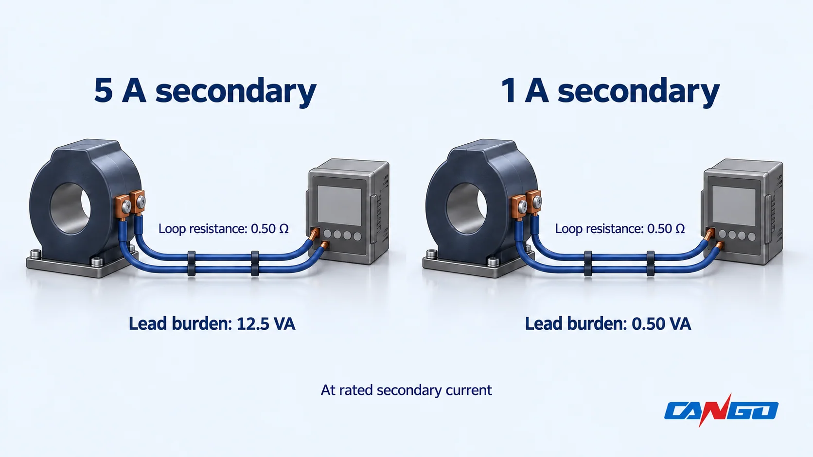
Assume the complete resistive lead loop is 0.50 Ω. Compare it at each rated secondary current:
| Quantity | 5 A secondary | 1 A secondary |
|---|---|---|
| Assumed complete lead-loop resistance | 0.50 Ω | 0.50 Ω |
| Lead-only calculation | 5² × 0.50 | 1² × 0.50 |
| Lead burden at rated secondary current | 12.5 VA | 0.50 VA |
| Assumed compatible receiver burden, for this example only | 0.20 VA | 0.20 VA |
| Illustrative lead-plus-receiver burden, assuming both are resistive | 12.70 VA | 0.70 VA |
The lead-only burden differs by a factor of 25 for the same resistance. That factor does not apply automatically to total installed burden: actual 1 A and 5 A receiver variants can have different specifications. Contact and test-facility contributions also remain to be added or demonstrated negligible.
Do not select the CT merely by rounding the total up to the next VA rating. Check accuracy over the actual burden range. In particular, the 0.70 VA example does not prove that an ordinary metering CT is certified at that burden. IEC’s January 2022 interpretation sheet addresses test-burden power factor and a minimum test burden of 1 VA in the measuring-accuracy clause it interprets. Request evidence for the proposed low-burden application. IEC Part 2 public preview and interpretation sheet.
Verify fault accuracy separately from fault withstand
A CT can meet a thermal withstand requirement while its secondary waveform is unsuitable for the intended protection function. Verify both questions.
Class and ALF do not replace the fault study
For a designation such as 5P20, review the 5P accuracy class, ALF of 20 and stated rated burden as one set of conditions. The ALF relates the rated accuracy-limit primary current to rated primary current. It is not a circuit-breaker interrupting rating. The BEST manual’s CT section explains the class/burden/ALF relationship; its example should not be copied as a generic purchase specification.
In the illustrative 600 A candidate, an ALF of 20 corresponds to 12 kA at the rated conditions. The assumed 16 kA fault is 26.7 times rated primary current. The label alone therefore does not establish the required accuracy at 16 kA. It also does not prove automatic failure: the actual burden, CT characteristics and relay requirements need assessment.
Increasing the primary ratio just to reduce the fault-current multiple can compromise other selection objectives. Recheck metering range and protection sensitivity before changing it.
Check the transient waveform and receiving relay
Symmetrical fault current is only part of the problem. DC offset and retained core flux can affect saturation. IEC’s public preview defines class P without a remanent-flux limit and describes its specified saturation behaviour for symmetrical short circuits. A class-P label is consequently insufficient evidence of performance for every offset fault waveform. IEC Part 2 preview, definition 3.1.204.
For the protection review, provide the relevant fault-current range, X/R or primary time constant, clearing/reclosing duty and relay-specific CT requirements. Ask for excitation data, secondary winding resistance at a stated temperature and any required remanence or transient-performance information. The assessment must consider the time for which the relay needs a usable signal. NPTEL explains how DC-offset flux adds to the AC flux and can drive the core into saturation. NPTEL: CT saturation and DC offset.
Separately confirm short-time thermal current with its duration and dynamic/peak withstand against the installation duty. Keep these values distinct from accuracy class and ALF. If the project uses an ANSI/IEEE specification, apply that framework explicitly; do not translate an IEC class into an apparently equivalent ANSI class by name alone.
Verify insulation, physical fit and secondary safety
A window that fits the conductor does not prove a suitable insulation arrangement. Confirm the CT construction, highest voltage for equipment where applicable, insulation levels and coordination with the primary conductor insulation and switchgear assembly. The position, supports, spacing and environmental conditions need review on the actual drawings.
Check the mounting envelope, aperture or primary terminals, conductor orientation, polarity, secondary terminal access, cable entry and core identification. Keep the CT schedule consistent with the equipment layout and protection-zone boundaries.
Never open the secondary of a conventional CT while primary current is flowing. Hazardous secondary voltage can develop. Specify suitable test/shorting facilities and an approved secondary-earthing design; isolation, testing and maintenance arrangements must be established by qualified personnel. FIST 3-8, Section 7, explains the open-secondary hazard. This selection guide does not provide an energized-work procedure. USBR FIST 3-8, Section 7.
Issue a CT schedule and request configuration evidence
Use one row for each core on each relevant CT, with panel and phase references. Keep shared installation data alongside it.
| Schedule field | Information to record |
|---|---|
| Panel, CT location, phase and core identity | Drawing references, protection boundary and assigned receiver/function |
| Ratio and current duty | Selected tap if applicable, rated primary/secondary current, frequency and continuous duty |
| Accuracy requirement | Metering class/current range and FS where required; protection class/ALF or scheme-specific requirements |
| External circuit | Calculated burden, applicable burden range/power factor, lead assumptions and receiver data |
| Fault-performance basis | Relevant fault study, excitation/winding-resistance data and relay assessment |
| Installation duty | Short-time current/duration, peak withstand, insulation and environmental requirements |
| Physical and service interfaces | Outline, conductor fit, polarity, terminal identification, earthing and test/shorting arrangements |
| Acceptance evidence | Offered CT datasheet, agreed tests, applicable reports and drawing approval responsibilities |
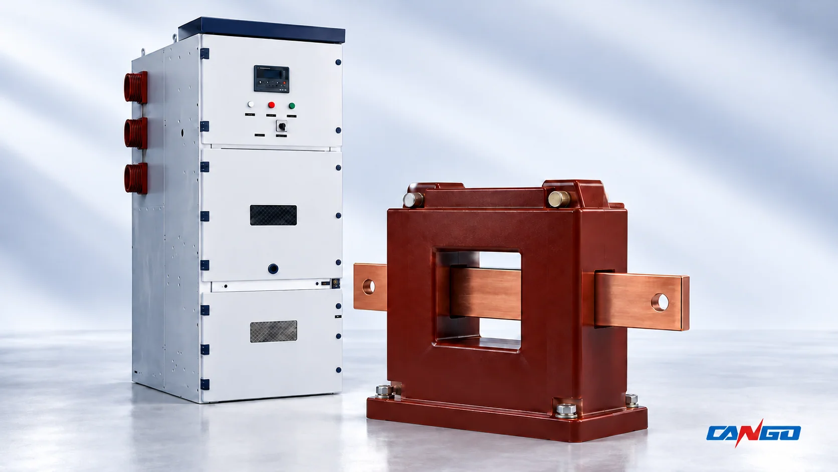
CANGO’s KYN28-12, KYN28-24 and KYN61-40.5 pages are starting points for discussing the corresponding switchgear configuration. Confirm the actual CT make/model, number of cores, ratio, class, burden and installation details in the project offer. A cabinet family or exterior photograph does not establish those options.
When requesting a panel quotation, add the CT schedule, receiver datasheets and fault-study basis to the MV switchgear quotation checklist. Send CANGO the project package so the offered configuration and supporting documents can be reviewed against the same requirements.
References
- IEC — IEC 61869-2:2012, Instrument transformers — Part 2: Additional requirements for current transformers; official public preview, including Interpretation Sheet 1, January 2022. Scope, visible definitions and the published interpretation were consulted.
- IEC — IEC 61869-1:2023, Instrument transformers — Part 1: General requirements, official publication summary.
- NPTEL / IIT Bombay — Power System Protection, Module 2, Lecture 5: CT equivalent circuit, excitation and saturation, and metering/protection duties.
- Brihanmumbai Electric Supply and Transport Undertaking — Information of the System Protection Department, 2021 document, CT section, PDF pages 42–43. Utility examples are not universal class or burden requirements.
- U.S. Bureau of Reclamation — FIST 3-8, Operation, Maintenance, and Field Test Procedures for Protective Relays and Associated Circuits, May 2011, minor revisions September 27, 2021; Sections 5.1 and 7.
- NPTEL / IIT Bombay — Power System Protection, Module 2, Lecture 7: CT saturation due to DC-offset current.
- CANGO product information — KYN28-12, KYN28-24 and KYN61-40.5 product pages, checked October 27, 2026. These are first-party equipment references, not CT qualification reports.