Select a voltage transformer (VT) for medium-voltage switchgear by the voltage it must measure, the devices it supplies and the conditions it must withstand. Define the sensing point and primary connection first; then specify the secondary voltage, accuracy and burden for each winding. Check earth-fault voltage duty, insulation, protection and physical interfaces before accepting the panel configuration.
The useful result is a VT schedule for each measurement point and secondary winding, supported by the single-line diagram, receiver data and the system earthing study. This guide covers conventional inductive VTs, also called potential transformers (PTs). Electronic voltage sensors and digital interfaces need their own compatibility review.
Three decisions deserve early attention:
- A bus-side VT and a feeder-side VT can observe different conditions when a breaker is open.
- A line-to-line voltage and a phase-to-earth voltage are different quantities; the specified ratio and receiver inputs must describe the same connection.
- A VT secondary supplies a voltage circuit. Adding instruments increases connected load, and an energized secondary must not be short-circuited.
Define the measurement point and the job
The single-line diagram establishes where voltage is measured. The protection and metering documents establish why it is measured and which signals are required.
| Measurement point | Typical question | Information to settle |
|---|---|---|
| Bus side | Is this bus energized, and what voltage do the bus instruments see? | Bus section, normal source arrangement, metering and voltage-supervision functions |
| Feeder or source side | Is voltage present on this feeder or incoming source? | Breaker position, possible backfeed, source detection and relay functions |
| A point used for synchronizing | Are the two sides suitable for closing under the approved scheme? | Both sensing locations, voltage/phase references and the relay inputs |
| Earth-fault or residual-voltage measurement | What signal does the protection scheme need during an earth fault? | Earthing method, required winding or derived signal, relay input and protection design |
The diagram below shows two possible measurement locations around a feeder breaker. With the breaker open, a bus voltage alone does not establish the voltage on the feeder side. Actual VT connection, isolation and protection are determined by the approved project drawings.
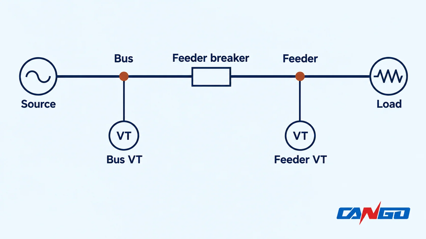
Voltage also supplies directional, synchronizing, metering and other functions; the receiver determines which quantities and accuracy are needed. NPTEL’s introduction to VTs describes their role in supplying voltage signals to protection devices. NPTEL: introduction to voltage transformers.
For the wider panel, use the MV switchgear single-line diagram guide to establish feeder and bus boundaries. The SLD symbol alone does not supply the complete VT winding schedule.
Specify the primary and secondary voltage together
Record system nominal voltage, highest system voltage, frequency, earthing arrangement and the VT’s intended primary connection. A phase-to-phase VT and a phase-to-earth VT do not see the same nominal voltage in a balanced three-phase system.
Also describe the secondary as a winding voltage and a receiver input, including whether the receiver expects phase-to-neutral, phase-to-phase or residual voltage. Confirm the winding polarity, phase sequence, connection and any separate secondary windings on the actual drawings. Do not assume that a label such as “110 V” answers all of those questions.
Example: an 11 kV system and a 110 V secondary
Assume a balanced three-phase system with 11 kV line-to-line and a three-VT phase-to-earth arrangement whose corresponding secondary phase voltages form a balanced 110 V line-to-line set. Assume ideal ratios and approved connections; these are illustrative values, not a CANGO offer.
| Quantity | Primary side | Corresponding secondary side |
|---|---|---|
| Line-to-line voltage of the balanced set | 11,000 V | 110 V |
| One phase-to-neutral voltage | 11,000 / √3 ≈ 6,351 V | 110 / √3 ≈ 63.5 V |
| Ideal ratio of one phase winding | 6,351 : 63.5 | Approximately 100 : 1 |
The √3 relationship applies to the stated balanced conditions. An earth fault can unbalance phase-to-earth voltages, so the table is not a fault-voltage prediction. The actual primary and secondary reference points, including their earthing, must be agreed for the project. A single VT connected phase-to-phase for an 11,000 V : 110 V example would also have an ideal 100:1 ratio, but the voltage measured by each winding is different from the phase-to-earth arrangement.
Before ordering, match the receiver’s voltage input and phase reference to the winding output. For revenue metering, obtain the metering authority’s applicable requirements and accuracy evidence rather than relying on a generic panel specification.
Match accuracy and burden to each winding
Metering and protection functions can have different accuracy needs and operating ranges. State the required accuracy class, voltage range, rated burden and power factor for each proposed secondary, together with the instruments it supplies. Separate windings or separate VT arrangements may be needed where the approved scheme requires them.
Designations such as 0.5 and 3P can appear in metering and protection specifications; they are not interchangeable purchasing shortcuts. An older UK National Grid VT specification uses combined class designations for its own applications. Its values are examples of a project specification, not a universal class selection for every MV panel. National Grid VT technical specification, 2016.
Also distinguish the rated output at the declared accuracy from any separately stated thermal output. A larger thermal VA value alone does not prove metering accuracy at the installed load. Ask for the offered winding’s actual accuracy range, test conditions and applicable certificate or report.
Worked example: three loads on one 110 V winding
Assume three compatible single-phase receiving inputs are connected in parallel across the same 110 V VT secondary winding. At 110 V, assume each load is resistive and has the stated burden:
| Receiving input | Assumed burden at 110 V |
|---|---|
| Meter | 3.0 VA |
| Protection relay | 2.0 VA |
| Voltage monitor | 5.0 VA |
| Total receiving-device burden | 10.0 VA |
At unity power factor, the illustrative total current is 10.0 VA ÷ 110 V ≈ 0.091 A. These values exclude conductor, fuse and contact effects. They are assumed device inputs for arithmetic, not CANGO test data or a recommendation to use those devices.
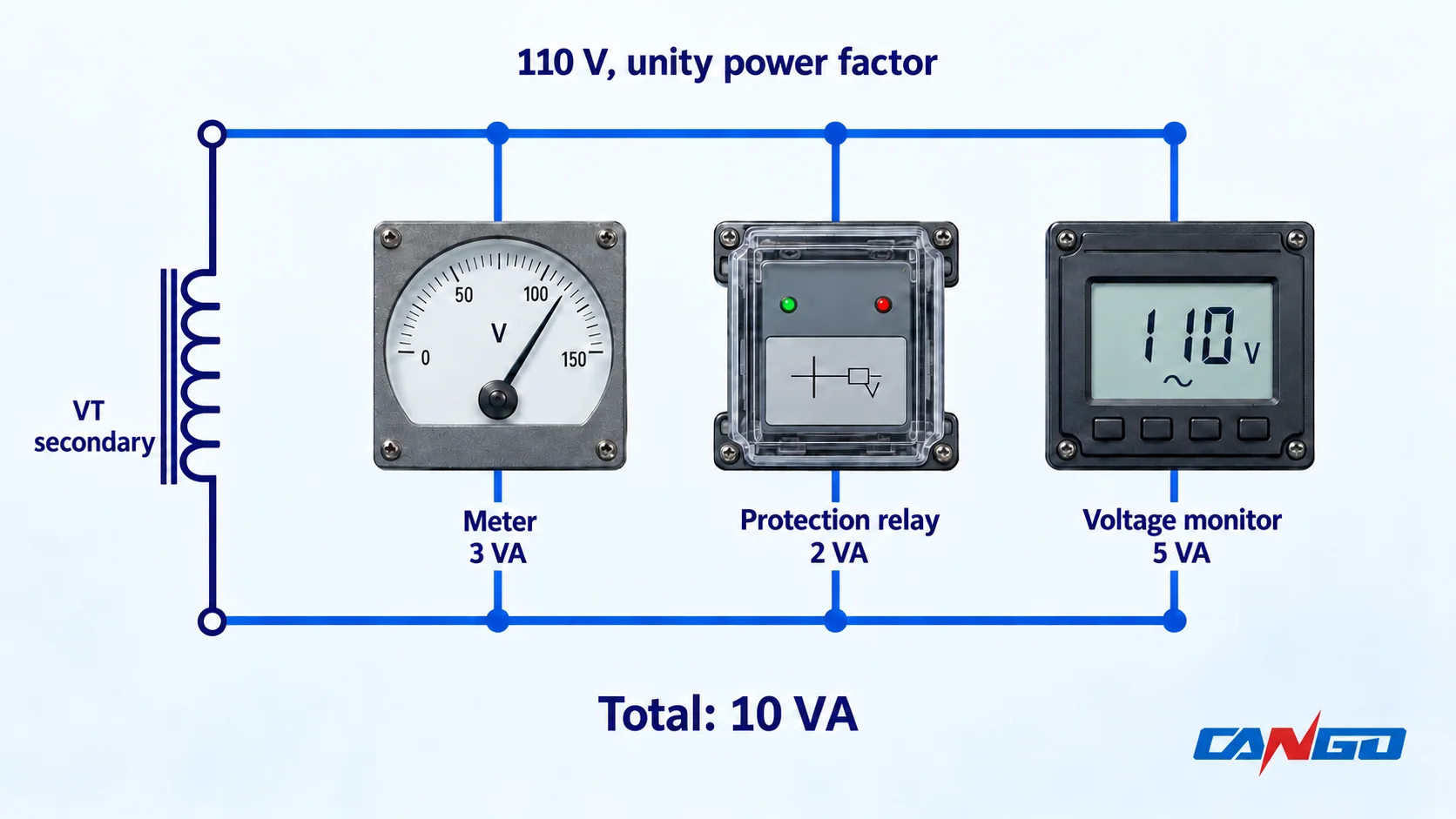
When loads have different power factors, use their complex power or impedance data at the specified voltage and evaluate the actual circuit; simply adding VA magnitudes can misstate the total. Include the secondary conductor route, fuse and test-contact impedances, and check the resulting voltage drop at each device. Multiple branches, mixed voltage inputs or three-phase arrangements need the actual drawings rather than this single-winding simplification.
Compare the installed burden and its power factor with the offered winding’s accuracy conditions, including any minimum and maximum burden applicable to that class and contract. A higher VA nameplate value alone does not establish accuracy at every connected load. USBR’s instrument-transformer guidance identifies the connected burden and includes methods for assessing both resistive and reactive parts. USBR FIST 3-8; USBR FIST 4-7, VT burden.
Check earth-fault voltage duty and insulation
For a phase-to-earth VT, an earth fault and the way the system neutral is earthed can change the voltage applied to the healthy phases. State the required rated voltage factor and its duration with the relevant earthing and fault-clearing assumptions. A normal 11 kV operating point is not enough to define that duty.
Request the VT’s primary insulation ratings and coordinate them with the system’s highest voltage, overvoltage study and switchgear assembly. Confirm ambient temperature, altitude, pollution, frequency and installation arrangement. The CT or breaker voltage rating is not, by itself, proof of the VT’s insulation suitability.
For an IEC-based inquiry, identify the exact standards and editions. IEC 61869-3:2011 covers new inductive VTs for measurement and protection at rated frequencies from 15 Hz to 100 Hz; the IEC publication page says it is read with IEC 61869-1:2007. IEC also publishes IEC 61869-1:2023 as a later general-requirements edition. Agree applicable editions and national adoption in the contract. A standard’s scope is not a certificate for an offered VT or assembled panel. IEC Part 3; IEC Part 1.
Where the network arrangement warrants it, include a ferroresonance assessment in the engineering review. Research on isolated-neutral systems describes how nonlinear inductive VT behaviour and network capacitance can interact during disturbances. The relevant network configuration, switching conditions and any mitigation need project-specific assessment; a damping component should not be specified as a universal cure. Martinez et al., 2022.
Coordinate isolation, protection and loss of voltage
Specify the VT’s fixed or withdrawable arrangement, primary and secondary protective devices, test interfaces, safe access and interlocks as applicable to the selected panel. A fuse or isolation device needs an approved rating and coordination study; do not assume a primary fuse alone resolves every secondary fault.
The protection team should decide how the scheme behaves if a VT fuse operates, a secondary circuit is disconnected or voltage signals become inconsistent. Loss of a VT signal is not, by itself, proof that the primary circuit is de-energized. Specify the required alarm, supervision, blocking or backup logic for the actual relays and operating modes.
Do not short-circuit an energized VT secondary. Unlike a conventional current-transformer secondary, it is a voltage circuit; a short can produce damaging current. A historical Vietnam MOIT/JICA technical draft states the different precautions for CT and VT secondaries. It is cited as engineering safety guidance, not as a current legal requirement for every jurisdiction. MOIT/JICA, 2013 draft, Article 344.
Provide an approved secondary-earthing and isolation design, identify possible backfeed paths, and leave work and testing to qualified personnel using the applicable procedures. For the different CT requirements, see current transformer selection for MV switchgear.
Prepare a VT schedule for the switchgear offer
Use one entry for each VT set and identify every secondary winding and its connected devices. Include shared system and physical data alongside the winding schedule.
| Schedule item | Information to provide or request |
|---|---|
| Measurement point and duty | Panel and drawing reference; bus, source or feeder location; metering, protection or synchronizing function |
| System basis | Nominal and highest voltage, frequency, neutral earthing, relevant earth-fault conditions and clearing time |
| Primary connection | Phase-to-phase or phase-to-earth arrangement, number of VTs and approved primary connection |
| Each secondary winding | Rated winding voltage and connection, assigned receivers, phase sequence and polarity |
| Accuracy and burden | Class, operating voltage range, rated and installed burden, power factor and accuracy evidence |
| Overvoltage and insulation | Voltage factor/duration, insulation and withstand requirements, environmental and site conditions |
| Panel and service interfaces | Mounting envelope, fixed/withdrawable arrangement, primary and secondary protection, interlocks, earthing and test access |
| Offer and verification | Exact VT make/model, drawings, applicable test reports, deviations, relay-interface and acceptance responsibilities |
CANGO’s KYN28-12, KYN28-24 and KYN61-40.5 pages provide starting points for a switchgear configuration discussion. Confirm the actual VT equipment, winding arrangement, voltage ratings and supporting evidence in the offer; the cabinet family alone does not establish those details.
Attach the VT schedule and receiver requirements to the MV switchgear quotation checklist and send CANGO the project information for configuration review.
References
- NPTEL / IIT Bombay — Power System Protection, Module 2, Lecture 8: Introduction to voltage transformers.
- National Grid — Voltage Transformers, Technical Specification TS 3.02.05 (RES), Issue 1, September 2016. The specification is an example for its stated applications.
- U.S. Bureau of Reclamation — FIST 3-8, Operation, Maintenance, and Field Test Procedures for Protective Relays and Associated Circuits, May 2011, minor revisions September 2021, Section 5.1; FIST 4-7, Commissioning Guide for Hydroelectric Facilities, August 2023, Section 6.1.36.2.1.
- IEC — IEC 61869-3:2011, Instrument transformers — Part 3: Additional requirements for inductive voltage transformers, and IEC 61869-1:2023, Part 1: General requirements, official publication summaries.
- Martinez, R., et al. — Acoustic Noise-Based Detection of Ferroresonance Events in Isolated Neutral Power Systems with Inductive Voltage Transformers, Sensors, 2022, 23(1), 195, DOI 10.3390/s23010195.
- Vietnam Ministry of Industry and Trade / Japan International Cooperation Agency — Technical Regulation, Volume 4: Operation and Maintenance of Power Plants and Grid, final draft for revision, June 2013, Article 344. This historical draft is cited for the stated safety principle, not as a current international code.
- CANGO product information — KYN28-12, KYN28-24 and KYN61-40.5, checked October 29, 2026. These are first-party cabinet references, not VT qualification reports.