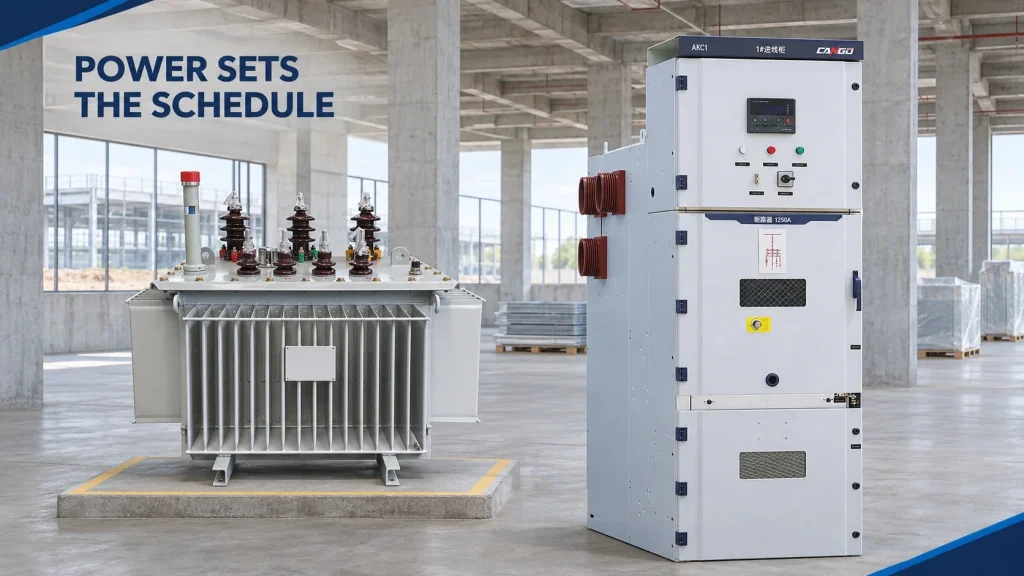
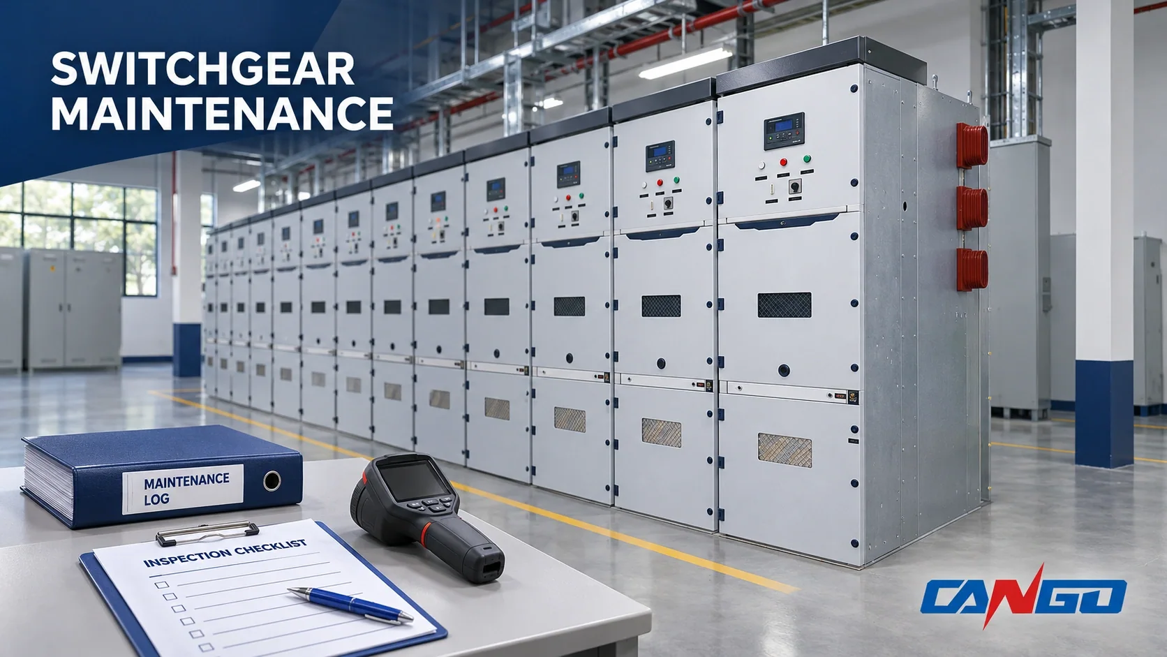
Short answer: Medium voltage switchgear maintenance has three layers: energized routine patrols, planned outage servicing, and condition- or event-triggered investigations. There is no universal fixed interval: start with the equipment manuals and operation counters, then adjust for environment and previous findings. Use the master schedule below to assign tasks, outage needs and the basis for each due date. The manufacturer’s instructions take precedence over every starting interval here.
Why there is no single fixed interval
IEC 62271-200 does not prescribe one fixed maintenance interval for the industry. Its assembly requirements must be used with the manufacturer’s instructions; the common maintenance framework in IEC 62271-1 considers operations, time in service, environmental conditions and diagnostic findings. Neither standard turns a cabinet designation into a fixed servicing interval. Record these four inputs for each asset:
- Manufacturer manuals: assembly, breaker, relay, instrument transformer and auxiliary-supply instructions may have different requirements.
- Operation count: frequent switching, interrupted current and fault duty change wear independently of elapsed time.
- Environment: dust, humidity, salt contamination and condensation change cleaning and insulation-inspection needs.
- Previous results: deterioration, recurring alarms and unresolved defects bring the next inspection forward.
Consider identical cabinets in a clean distribution room and a cement plant. The first may remain clean between inspections; the second may accumulate conductive contamination or obstruct ventilation. Copying the first schedule to the second ignores the exposure that maintenance must control.
A breaker used frequently can reach its manual’s operation-based service point before its calendar date. A lightly operated breaker still needs calendar and condition review: its counter does not reveal corrosion, lubricant deterioration or a failing control supply. Use whichever applicable trigger comes first. The verified manufacturer schedules below illustrate this approach; they are not CANGO service instructions.
Master maintenance schedule
These are typical starting intervals for normal environments, not mandatory intervals or permission to defer a defect. Shorten them for severe conditions. Where a manufacturer manual conflicts with this table, follow the manual. Enter an actual approved date against every task before issuing the outage plan.
The annual and semiannual examples below are anchored to the SafeGear maintenance manual, IB3.2.5-7C, maintenance section; its relay review example is biennial. They demonstrate one manufacturer’s program, not interchangeable instructions for other equipment. Entries without a numerical interval deliberately await the applicable component manual or condition assessment.
| Task | Tier | Typical starting interval | Energized or outage required | Basis |
|---|---|---|---|---|
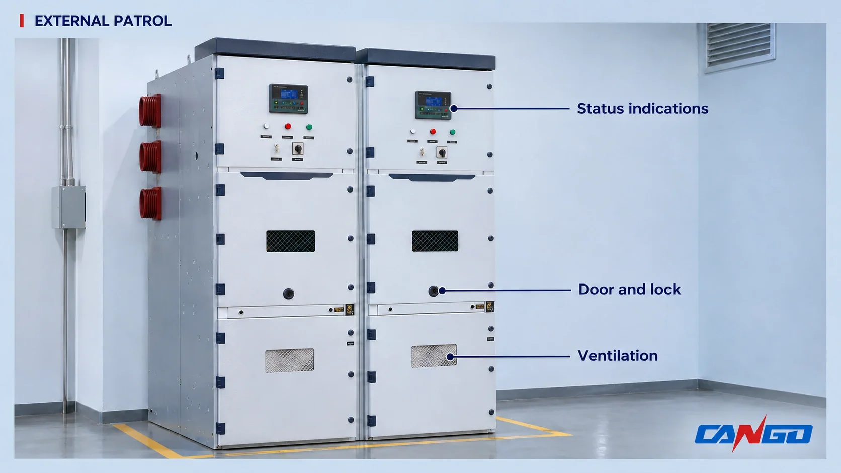
| External patrol: indications, alarms, sounds, odors, doors, ventilation and heater status | Patrol | Every scheduled operator round; semiannual documented inspection example | Energized, external observation only | Calendar; manufacturer manual |
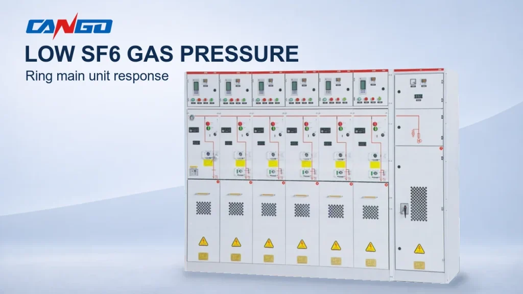
| Gas-compartment density indication record, GIS/RMU only | Patrol | Each scheduled round where readable; investigate alarms immediately | Energized, external indication only | Condition; manufacturer manual |
| Infrared survey under representative load | Trigger-based | Set from thermal history; repeat after suspected heating or load change | Energized through approved viewing provisions | Condition |
| Relay event/trip review and approved-setting comparison | Patrol | After every operation/alarm; include scheduled record review | Energized, approved interface only | Condition; operation count |
| Station DC, battery and charger checks | Patrol | At the DC-system manual interval; include outage readiness review | Approved accessible indications; intrusive work separately isolated | Manufacturer manual |
| Cleaning and insulation inspection | Periodic service | Annual outage example; earlier with contamination or moisture | Outage required | Calendar; condition |
| Withdrawable truck, contact fingers and secondary plugs | Periodic service | Annual inspection example; contact servicing at breaker manual interval | Outage and defined isolation required | Manufacturer manual; calendar |
| Mechanism lubrication, functional checks, charging and counter | Periodic service | Manual calendar or operation limit, whichever occurs first | Outage; controlled test conditions | Manufacturer manual; operation count |
| Interlocks and earthing-switch functional checks | Periodic service | Include planned service outage; exact interval from manual | Outage and approved test boundaries | Manufacturer manual |
| Busbar/cable joint inspection and suspect-joint remeasurement | Periodic service | Annual visual example; investigate thermal evidence sooner | Outage required for internal access | Calendar; condition |
| Insulation-resistance and conductive-loop-resistance tests | Periodic service | At approved test-program interval; after relevant defects or repairs | Outage and test isolation required | Manufacturer manual; condition |
| Breaker timing and mechanical characteristics | Periodic service | Breaker manual interval or operation limit; sooner after abnormal operation | Outage; controlled test conditions | Manufacturer manual; operation count |
| Relay secondary injection and CT/VT secondary-circuit verification | Periodic service | Biennial relay-review example; device program determines actual scope | Outage or separately approved protection-test isolation | Manufacturer manual; calendar |
| Vacuum integrity and contact wear | Periodic service | Manufacturer method and operation/wear trigger; no generic year limit | Outage; breaker isolated as specified | Manufacturer manual; operation count |
| Partial-discharge assessment, where monitoring/test provision exists | Trigger-based | Alarm, adverse trend or approved diagnostic program | Online or outage, depending on installed method | Condition |
| Breaker or mechanism overhaul | Overhaul | Manufacturer wear/operation limit or investigation finding | Outage required | Operation count; condition; manufacturer manual |
Inspect and remeasure suspect joints; retighten only where the manufacturer specifies it, using its procedure. Routine retightening is not a universal maintenance task.
Do not convert the annual example into an annual requirement for every electrical test. Likewise, a scheduled outage does not authorize dismantling sealed compartments. For maintenance-scope boundaries, use the AIS versus GIS guide.
Inspection checklist by compartment
Mark each applicable item complete, defective or not applicable, with evidence. Access to primary compartments requires the approved outage arrangements. A tick without an observation or test reference does not close a defect.
Busbar and cable compartments
- [ ] Look for dust bridges, moisture films or deposits on insulation; concentrated contamination requires investigation and approved cleaning.
- [ ] Inspect exposed insulation for cracks, tracking paths, erosion or burn marks; record location and extent.
- [ ] Examine accessible joints for discoloration, corrosion or displaced witness marks; compare with thermal and resistance records.
- [ ] Check cable supports and terminations for movement, strained connections, damaged screens or deteriorated stress-control surfaces.
- [ ] Inspect shutters, barriers and seals for damage or missing parts; identify any loss of segregation.
- [ ] Check cable-entry sealing and pest evidence; droppings, nesting material or open penetrations require corrective action.
Circuit-breaker truck and operating mechanism
- [ ] Inspect primary contacts and tulip fingers for uneven wear, burning, damaged plating or displaced springs.
- [ ] Examine truck guides, wheels and racking interfaces for binding, distortion or debris; investigate unexpected resistance.
- [ ] Inspect secondary plugs, multipin connectors and latches for bent pins, poor engagement, heat damage or broken locking parts.
- [ ] Compare opening, closing and charged-spring indications with the actual approved test state; conflicting indications are defects.
- [ ] Record the operation counter and mechanism behavior; sluggish movement, incomplete charging or repeated motor running needs investigation.
- [ ] Check lubricant condition and specified lubrication points against the manual; do not apply a generic grease or lubricate contacts indiscriminately.
Protection, control and secondary circuits
- [ ] Review trip, disturbance and alarm records for unexplained operations, missing events or recurring supervision alarms.
- [ ] Compare active relay settings and configuration identifiers with the approved issue; investigate unauthorized differences.
- [ ] Inspect secondary wiring, terminal identification and connector engagement for abrasion, heat damage or loose components.
- [ ] Check CT test links, shorting arrangements and designated secondary earth connections against approved drawings; discrepancies require correction before release.
- [ ] Check VT fuses, isolation arrangements and secondary-circuit identification for damage or disagreement with the drawings.
- [ ] Review charger alarms, battery condition, DC distribution and trip-supply supervision; unresolved control-power faults affect release.
For circuit-specific documentation, link the work order to the CT guide and VT guide. This checklist does not replace their circuit drawings or device instructions.
Earthing switch and interlocks
- [ ] Compare earthing-switch indications with verified mechanical position; a mismatch is unacceptable.
- [ ] Inspect operating linkages and position indicators for looseness, bending or incomplete travel.
- [ ] Test the documented interlock sequence under approved isolated conditions; record any prohibited operation that becomes possible.
- [ ] Check key locks, door interlocks and truck-position interlocks for missing parts, bypasses or forced damage.
- [ ] Examine accessible earth connections for corrosion, broken conductors or insecure attachment.
- [ ] Confirm test changes, temporary keys and bypass arrangements are accounted for before release.
Enclosure, heaters and environment
- [ ] Inspect door fit, hinges and locks for deformation, corrosion or gaps that compromise enclosure integrity.
- [ ] Check ventilation paths and filters for obstruction; identify deposits that restrict cooling.
- [ ] Verify heaters, thermostats and anti-condensation indications by the approved method; failed heaters require action.
- [ ] Look for water staining, condensation droplets and corrosion below entry points; investigate the moisture source.
- [ ] Inspect pressure-relief paths and designated clearances for blockage or unauthorized storage, using the assembly drawings.
- [ ] Check room cleanliness and penetrations for salt deposits, cement dust and pest entry; record exposure changes.
Gas-insulated compartments (GIS and RMU only)
- [ ] Record the identified compartment’s density indication and alarm state; investigate movement outside the manufacturer’s acceptable indication.
- [ ] Compare readings with earlier records and applicable temperature compensation; an unexplained decline requires leak assessment.
- [ ] Inspect accessible seals, fittings and enclosure surfaces for damage or corrosion without disturbing gas connections.
- [ ] Review density-monitor alarms and supervision records; unexplained alarms or missing indication require investigation.
- [ ] Arrange leak checking by the approved method when indicated; repeated topping-up is not a substitute for locating a leak.
- [ ] Keep gas handling with trained, appropriately certified personnel and approved recovery arrangements; do not open sealed compartments as routine cleaning.
IEC 62271-4:2022 covers handling procedures for gases used in insulation and/or switching. Apply it with the compartment manufacturer’s instructions; this checklist does not provide gas-handling procedures or a regulatory timeline.
Tests and how results are judged
Establish the test connection, instrument identity, environmental conditions and relevant operating state before comparing readings. A result collected differently from the baseline may require technical interpretation before it can support a trend. The applicable manufacturer instructions govern test methods and limits.
| Test | What it detects | How the result is judged |
|---|---|---|
| Insulation resistance | Insulation contamination, moisture or deterioration | Compare with manufacturer requirements and commissioning baseline under comparable conditions; investigate adverse change before release. |
| Contact (loop) resistance | Deterioration in the measured conductive path | Compare with manufacturer values and the same-path baseline, accounting for test setup; locate any unexplained increase. |
| Breaker timing/mechanical characteristics | Abnormal operating time, pole synchronism or mechanism behavior | Compare opening/closing times and relevant characteristics with manufacturer limits and commissioning traces. |
| Relay secondary injection | Protection-element, logic and configured-function performance | Compare operation with approved settings, manufacturer tolerances and baseline test records; resolve unexpected behavior. |
| Infrared thermography | Abnormal heating at accessible observed surfaces | Compare manufacturer guidance and comparable-load baseline images; investigate unusual phase patterns or persistent hotspots. No universal temperature band is assumed. |
| Partial discharge, where fitted | Discharge activity detectable by the installed method | Compare manufacturer interpretation rules and method-specific baseline/trends; investigate unexplained activity with specialist review. |
| Vacuum integrity, manufacturer method | Loss of interrupter integrity detectable by that method | Apply the prescribed manufacturer procedure and acceptance values, retaining baseline results where comparable; do not substitute a generic test voltage. |
If any result deteriorates materially from baseline, identify the cause before re-energization. Recording the number alone is not acceptance. Contact resistance cannot identify a suspect joint unless the measured path and connections are documented. Timing results also need the relevant control-supply and mechanism conditions recorded.
PD assessment applies only where suitable online monitoring or an approved offline method exists. It is not a compulsory test for every cabinet. Keep the method and insulation context with the record; see the GIS partial-discharge article.
Trigger-based checks: when the calendar does not apply
- After a short-circuit trip: preserve relay records, identify the faulted circuit and interrupted duty, then assess affected breaker, joints, insulation and protection before release.
- After abnormal protection operation: reconcile the event with approved settings, CT/VT circuits, trip logic and control supply. An unexplained trip remains an open defect.
- After flooding or severe condensation: keep affected equipment out of service pending assessment of contamination, insulation, mechanisms and secondary devices. Dry appearance alone does not establish fitness.
- Before return after prolonged shutdown: assess storage exposure, corrosion, heaters, mechanisms, protection and DC readiness; use the applicable recommissioning instructions.
- At commissioning: establish the baseline for later comparisons, including test setup, original readings, timing records, settings and photographs. Without it, a later result cannot be assessed reliably as an improvement or deterioration.
Red flags: do not re-energize until checked
- Discharge sounds or unusual odors may indicate insulation distress requiring investigation.
- Tracking, erosion or burned insulation indicates damage that cleaning alone may not resolve.
- Low SF6 density indication or alarm means compartment operating conditions need manufacturer-directed assessment.
- Failed, sluggish or inconsistent breaker operation can prevent dependable fault interruption.
- Persistent thermal hotspots may identify a deteriorating connection or abnormal loading.
- Failed relay tests or unexplained setting discrepancies undermine the intended protection response.
- Failed interlocks or uncertain earthing-switch position compromise the approved operating sequence.
Each red flag needs a named owner, an investigation record and an authorized release decision. The next scheduled outage date cannot close it.
Safety and outage planning
Maintenance must be performed by qualified personnel using the site’s isolation, proving-dead, earthing and permit procedures. This article is a planning and checklist tool, not an energized-work tutorial. Define all sources, backfeeds, adjacent live compartments and secondary test boundaries before assigning work.
Interlocks constrain prohibited operating sequences; an earthing switch supports the approved earthing arrangement. Neither replaces isolation verification or a permit. See earthing switches and interlocks.
Confirm the actual compartment-access and LSC arrangements from assembly documents; the MV switchgear guide provides the terminology. LSC classification alone does not authorize work beside energized equipment.
What to record after every maintenance visit
| Record field | Required content |
|---|---|
| Asset identity | Asset number, cabinet model, serial reference and circuit name |
| Operation counter | Current reading, previous reading and relevant trip/event references |
| Work and original values | Tasks completed, raw test results, instrument and method identifiers |
| Previous baseline | Commissioning or accepted previous results, with comparable test conditions |
| Findings and treatment | Defects, location/photos, corrective work, unresolved items and release authority |
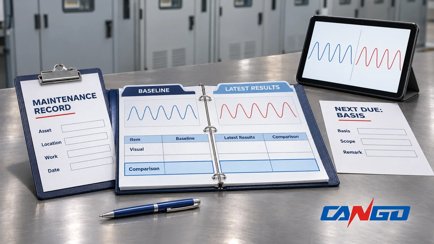
| Next due date and basis | Manual reference, operation limit, calendar decision or condition trigger, with responsible owner |
The record connects the schedule to the asset. Without baseline records, the interval table cannot function as a defensible maintenance program. If no reliable commissioning record exists, document the limitation and establish an assessed reference during an approved inspection; do not label an unexplained present condition as a healthy baseline.
CANGO equipment this checklist applies to
Use this framework, adapted to the supplied configuration, for CANGO KYN28-12, KYN28-24, KYN61-40.5 and XGN17-40.5 switchgear, and the GTXGN-12 solid-insulated, SRM-12 gas-insulated, XGN15-12 and HXGN17-12 RMU families. Gas-compartment tasks apply only where that compartment exists.
Start with the product documentation for KYN28-12 or SRM-12, then use the manuals delivered with the actual cabinet. Model-specific instructions govern maintenance. For interrupter condition and life considerations, use the vacuum and SF6 breaker article; this whole-assembly checklist does not duplicate its comparison.
FAQ
How often should medium voltage switchgear be serviced?
There is no universal fixed maintenance interval. Start with the assembly and component manuals, then consider operation counts, environment and previous inspection results. Typical starting layers are operator patrols, planned outage service and condition-triggered checks. The manufacturer example used here includes semiannual documented inspections and annual servicing, but those values are not CANGO requirements. Shorten the schedule for severe exposure and use the applicable manual or operation limit whenever it requires earlier attention.
Which switchgear checks can be done while the switchgear is energized?
External patrols can review accessible indications, alarms, unusual sounds or odors, enclosure condition and installed monitoring displays within the site’s approved access rules. Infrared surveys require representative load and an approved viewing arrangement; they do not justify opening energized compartments. Gas-density indications may be recorded externally where the design permits. Intrusive inspection, cleaning and electrical testing need separately defined isolation and authorization. Keep a clear distinction between observing equipment and performing work on it.
What tests are done during a medium voltage switchgear maintenance outage?
The approved outage scope may include insulation resistance, conductive-loop resistance, breaker timing, protection secondary injection and secondary-circuit verification. Add vacuum-integrity checks only by the breaker manufacturer’s method, and PD testing only where a suitable diagnostic method exists. Select tests from the assembly and component manuals, operating history and identified defects. Record original results and conditions so they can be compared with commissioning records. Not every listed test is required at every outage.
How do you judge whether a test result is acceptable?
Compare the result with the relevant manufacturer’s requirements and the commissioning or accepted previous baseline under comparable conditions. Protection tests also need the approved settings and configured logic. Record test connections, equipment state and measurement conditions; a changed method can invalidate a simple trend comparison. Do not apply a universal insulation-resistance, loop-resistance or timing threshold. If a result deteriorates materially, investigate and resolve its cause before an authorized return-to-service decision.
What should be checked before switchgear is returned to service after a fault trip?
Preserve the event records and establish the fault cause and affected equipment first. Assess breaker operation and interrupted duty, insulation, joints, protection response, secondary circuits and control-power readiness using the applicable manuals. Complete the necessary inspection and tests, compare findings with manufacturer requirements and baseline records, and close relevant defects. Verify restoration of test links, interlocks and documented operating arrangements through the approved release process. A successful reset alone does not establish readiness.
References
- IEC, IEC 62271-1:2017, common specifications; maintenance planning is implemented through the equipment instructions.
- IEC, IEC 62271-200:2021, metal-enclosed switchgear assembly scope and maintenance framework; used with IEC 62271-1 common specifications and the applicable manufacturer’s instructions.
- ABB, SafeGear installation and maintenance manual, IB3.2.5-7C, maintenance section: manufacturer-specific semiannual, annual and biennial examples, not CANGO intervals.
- IEC, IEC 62271-4:2022, scope of gas-handling procedures for insulation and/or switching.