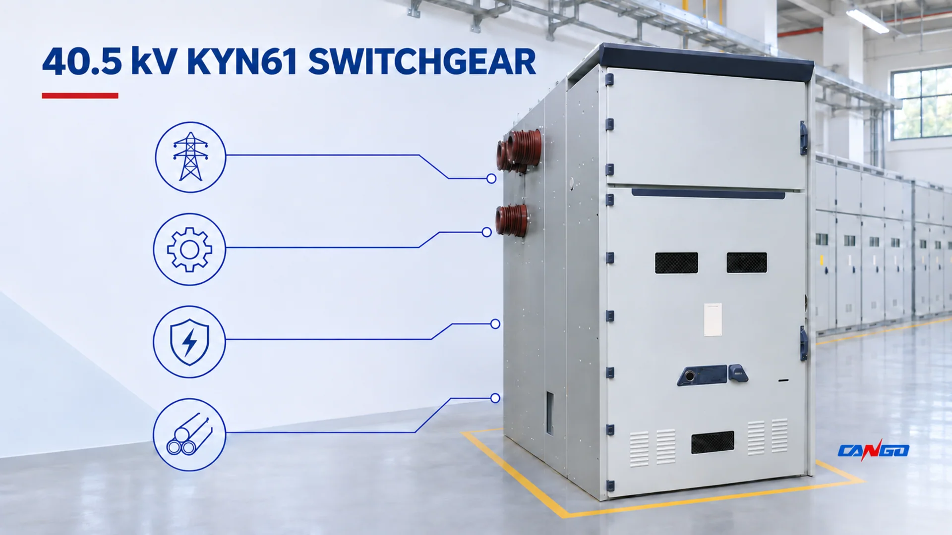
40.5 kV KYN61 switchgear is indoor, withdrawable AC metal-enclosed equipment for receiving and distributing electrical power. CANGO lists power plants, substations, and industrial and mining distribution systems as application areas for KYN61-40.5. The model combines a removable handcart arrangement with separate busbar, cart, cable and relay instrument rooms. CANGO KYN61-40.5 product information
Start the selection with the job the lineup must perform: which circuits it will connect, how they will be protected, and how the equipment will be accessed for maintenance. Then match the offered voltage, current and fault duties to the project studies, and resolve the cable and control interfaces. CANGO’s published 40.5 kV, 50 Hz schedule provides the initial screening data.
This guide helps EPC teams, utility and industrial buyers, and electrical contractors assess application fit and build a comparable RFQ. It follows the decision from the model code and ratings through compartment interfaces to room layout and documentation. Final engineering selection and approval remain with the responsible project team.
What KYN61-40.5 identifies
CANGO’s model graphic explains the construction and voltage designation. Read the code alongside the circuit schedule and arrangement drawing:
| Code element | Published meaning | What the buyer still needs to define |
|---|---|---|
| K | Metal armored | The exact enclosure construction and the project’s applicable classification or terminology |
| Y | Removable handcart type | The breaker cart, handling arrangement and interface compatibility |
| N | Indoor | The room, environmental conditions, access and installation design |
| 61 | Design serial number | The detailed arrangement and ordered circuit configuration |
| 40.5 | Rated voltage in kV | The nominal and maximum system voltage, insulation basis and applicable project standards |
The product page also asks the buyer to confirm the main-switch type, operating-mechanism type, special-use conditions, rated current and short-circuit breaking current. Those items are not resolved by the five code elements. The code identifies the family; the single-line diagram, panel schedule, component list and approved drawings define the offer.
CANGO uses the term “metal-enclosed” in the product description and “metal armored” in the model explanation. Buyers should therefore avoid treating a marketing term or model letter as proof of a particular construction class. The metal-clad versus metal-enclosed switchgear comparison explains why the terminology needs to be tied to the actual construction, partition arrangement and project specification.
Start with the system voltage, frequency and insulation basis
Three voltage values should not be collapsed into one:
- Nominal system voltage is the voltage by which the network is identified.
- Maximum system voltage is the highest voltage that can occur in the network under the defined operating conditions.
- Equipment rated voltage is the voltage class declared for the equipment.
CANGO’s KYN61-40.5 page publishes a rated voltage of 40.5 kV. That does not establish that every 40.5 kV nominal network, every earthing arrangement or every insulation-coordination case is automatically covered. The project must state its system-voltage definition, earthing arrangement, temporary and lightning overvoltage basis, altitude and other conditions that affect insulation coordination.
The page publishes 50 Hz. It does not state a 60 Hz offering on the checked page. A project with a 60 Hz requirement must obtain written confirmation rather than assuming that a standard 50 Hz configuration can be applied unchanged.
The applicable standards framework also needs to be stated by edition and project role. IEC 62271-1:2017+AMD1:2021 is the common specification for AC switchgear and controlgear, covering indoor and outdoor equipment at rated voltages above 1,000 V and service frequencies up to and including 60 Hz. IEC 62271-200:2021+AMD1:2024 applies to prefabricated AC metal-enclosed switchgear and controlgear assemblies above 1 kV through 52 kV, at service frequencies up to and including 60 Hz and for indoor or outdoor installation. IEC 62271-1 publication information and IEC 62271-200 publication information identify the scope and editions.
Those scope statements frame the equipment class. They do not prove that a particular KYN61-40.5 arrangement, rating combination, partition system or project installation meets every applicable requirement. The medium-voltage switchgear types and ratings guide can help separate equipment-family questions from project-specific selection work.
Read the published rating schedule as a linked set
The KYN61-40.5 product page publishes the following screening data:
| Published item | KYN61-40.5 page | Buyer check |
|---|---|---|
| Rated voltage | 40.5 kV | Nominal and maximum system voltage, earthing, insulation basis and project standard |
| Rated frequency | 50 Hz | Confirm the project frequency; no 60 Hz claim is made on the checked page |
| Rated current | 1250, 1600 or 2000 A | Normal and contingency load, ambient conditions, busbar arrangement and exact circuit schedule |
| Rated short-time withstand current | 20, 25 or 31.5 kA | Fault-current magnitude, duration and evidence for the exact offered assembly |
| Rated peak withstand current | 50, 63 or 80 kA | Peak fault duty and the controlled rating schedule |
| Rated power-frequency withstand voltage | 95 kV for 1 min | Exact insulation schedule, system earthing and applicable project standard |
| Rated lightning impulse withstand voltage | 185 kV | Exact insulation-coordination basis and configuration evidence |
| Rated short-circuit duration | 4 s | Coordination of fault duration with the project study and offered equipment |
| Enclosure protection | IP3X | The stated enclosure entry only; not a complete environmental or installation classification |
The table is a screening aid, not a pick-one-row catalogue. The current, short-time, peak, insulation and breaker ratings must be reviewed as a linked schedule. A high current value does not automatically resolve temperature rise, busbar loading or cable-interface conditions. A short-time withstand value does not by itself establish the breaker’s breaking duty or the performance of the complete protection scheme. The product page separately asks the buyer to confirm the short-circuit breaking current and the selected main switch.
The two withstand rows also require careful reading. The page lists short-time withstand current and peak withstand current separately. Do not invent a pairing between one short-time value and one peak value unless the supplier’s controlled schedule identifies that relationship for the offered configuration. The same rule applies to the insulation values: ask for the complete table and the conditions under which each entry applies.
IP3X describes a published enclosure-protection entry. It does not prove resistance to every site condition. Condensation, humidity, dust, corrosive atmosphere, altitude, seismic demand, ventilation and indoor temperature all need separate treatment in the project specification and the supplier’s review.
Configure circuits, busbars and compartments together
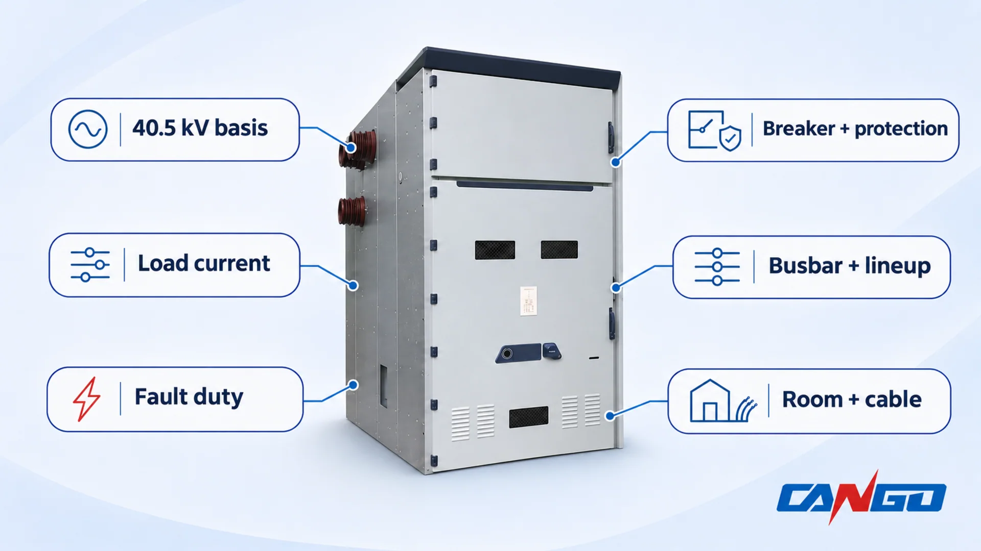
The single-line diagram defines the electrical job of each panel. A KYN61-40.5 lineup may need to represent incomers, outgoing feeders, bus sections, transformer circuits, measurement points and spare or future circuits, but the exact arrangement must come from the project. For each circuit, identify the switching device, current and voltage transformers, protection, metering, earthing, interlocks, control devices and cable interface.
The medium-voltage switchgear single-line diagram guide explains how to read the electrical relationships before converting them into a panel schedule. Do not allow a quotation to be built from a list of panel names alone. The offer should return the proposed primary scheme, device schedule and busbar arrangement for every circuit.
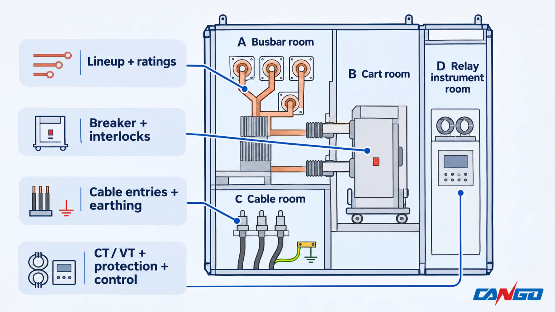
CANGO’s KYN61-40.5 structure drawing identifies four functional rooms. The drawing is useful because it turns the family name into interfaces that the electrical, civil, cable, protection and operations teams can review.
| Documented room | Main project interface | Evidence to request |
|---|---|---|
| Busbar room | Lineup current, main and branch busbar arrangement, section continuity, connections between panels and future extension | Busbar schedule, joint arrangement, partition information and applicable ratings for the offered lineup |
| Cart room | Exact breaker, withdrawable cart, primary and secondary contacts, position indication, interlocks and handling | Breaker model, cart compatibility, mechanism data, interlock schedule and operating/access information |
| Cable room | Cable entry, number and type of cables, terminations, supports, earthing, current transformers and surge-arresting provision where specified | Cable-entry and termination drawing, available termination envelope, earthing interface and installation requirements |
| Relay instrument room | CT/VT circuits, protection and metering devices, terminal blocks, auxiliary supply and communications | Device schedule, CT/VT data, terminal and wiring schedule, control-power requirements and communication interface |
The room names do not prove that every component in the drawing is included in a particular offer. The approved configuration drawing and bill of materials decide the scope. A withdrawable breaker or cart from another family or rating is not automatically interchangeable. Mechanical fit, primary contacts, secondary connections, earthing and interlocks all require a compatibility review.
Busbar planning should be reviewed with the full lineup rather than one panel in isolation. Confirm the main-busbar current basis, branch connections, the interface at each end of the lineup, the proposed future extension, and the method for maintaining or isolating a section. The project also needs to state whether the busbar arrangement and panel order in the quotation are fixed or provisional.
Specify the breaker, CT/VT, protection and control as one scheme
The circuit-breaker is one component inside the assembly, not a substitute for the assembly specification. Obtain the exact breaker model, rated voltage, rated current, short-circuit breaking and making duties, operating mechanism, trip and closing circuits, auxiliary contacts, position indications and any required monitoring. Confirm that the breaker is compatible with the KYN61-40.5 cart, primary contacts, secondary plug, earthing arrangement and interlocks.
IEC 62271-100:2021+AMD1:2024 applies to three-phase AC circuit-breakers for indoor or outdoor installation and for operation at 50 Hz and/or 60 Hz on systems above 1,000 V. The official publication page identifies the consolidated edition and scope. It does not establish that a particular CANGO breaker has a stated rating or test result. IEC 62271-100 publication information
Current and voltage transformers need a separate schedule. Define the ratio, accuracy class, burden, short-time current capability, location, polarity and wiring requirements for each core and each circuit. The assembly’s current rating does not automatically establish the CT duty, and the breaker rating does not establish the VT or protection performance. The current-transformer selection guide and voltage-transformer selection guide cover the inputs that belong in those reviews.
Protection functions and settings must follow the approved protection study and operating philosophy. The switchgear supplier may provide relays, test terminals, wiring, CT/VT interfaces and a requested communication protocol, but that does not transfer protection-setting responsibility to the equipment supplier. Ask for the device schedule, terminal schedule and the boundary between supplier-configured and project-configured functions.
Earthing and interlocks must be described as a scheme. Confirm the earthing-switch arrangement, cable-test and earthing points, operating sequence, lock and key provisions, position indications and the method for proving dead before work. The earthing-switch functions and interlocks guide explains the review questions; it does not authorize a switching procedure.
Control power and communications belong on the same interface schedule. Identify the auxiliary supply, trip and closing supplies, battery or charger boundary, changeover behavior, relay and meter protocols, event recording, time synchronization and the signals required by the plant control system. If these items are left to the end of the order, the primary equipment may be mechanically complete while the operating scheme remains unresolved.
Define the switchgear-to-installation interface
IEC 61936-1:2021 provides requirements for the design and erection of AC power installations above 1 kV and nominal frequency up to 60 Hz. Its public scope also states that it does not apply to the design of prefabricated, type-tested switchgear or high-voltage/low-voltage prefabricated substations, for which separate standards exist. The practical lesson is that the KYN61-40.5 assembly documentation and the installation design are related but separate deliverables. IEC 61936-1 publication information
For KYN61-40.5, the installation review should establish:
- The indoor room location, access routes and operating layout.
- The exact general arrangement, panel order, front and rear access needs and door or panel movement.
- The transport, lifting, delivery and replacement route into the room.
- Cable entry direction, termination space, cable support, sealing and earthing interfaces.
- The earthing connection between the switchgear and the installation earthing system.
- Auxiliary power, control cables, communications, metering and SCADA interfaces.
- The method for handling the withdrawable cart during inspection and maintenance.
- The future-extension boundary and the interface with adjacent panels.
- Any fire, ventilation, environmental or site-specific requirement that affects the equipment enclosure or room.
Do not use a dimension copied from a different KYN61 drawing, another voltage class or another supplier’s arrangement. The approved general arrangement must be reviewed against the actual room and cable design. Numerical clearances, aisle widths, cable sizes and installation details remain project-engineering decisions.
The drawing package should also show how the supplier’s scope terminates. Identify the cable-side and busbar-side limits, the auxiliary-terminal limits, the earthing-terminal limits and the responsibility for interconnection between panels. A clear interface schedule prevents the switchgear, transformer, cable and control packages from each assuming that another party will close the same gap.
Evaluate applications conditionally
CANGO’s listed application areas lead to different selection priorities. Start with the circuit’s role on the single-line diagram, then identify the operating and site conditions that could change the offer. The following review points translate those application areas into procurement questions.
Power plants and utility substations
For a plant or substation distribution room, first identify whether each panel is an incomer, outgoing feeder, transformer circuit or bus section. This determines the primary scheme and the interfaces that must be agreed with the network, transformer and protection teams. Ask the supplier to return a panel schedule that maps each circuit to its breaker, instrument transformers, protection and control requirements.
Give particular attention to the permitted source and bus-section operating states. If the project includes more than one source or a bus tie, provide the study results and interlocking requirements for the allowed configurations. The offer should identify which duties it covers and which control or protection interfaces belong to another package.
For a utility connection, obtain the network owner’s metering, protection, communication and acceptance requirements before agreeing on the equipment scope. Use the utility distribution networks solution for the broader supply context and the utility switchgear guide for network-side review questions.
Selection focus: a circuit-by-circuit match to the owner’s operating scheme, with the 40.5 kV insulation basis and required duties confirmed for the offered assembly.
Industrial plant intake and distribution expansion
For a plant intake or an additional distribution lineup, start with the load schedule and the boundary between the new equipment and the existing installation. State which circuits serve transformers or downstream distribution boards, which are reserved for expansion, and whether any connection to an existing busbar is required. KYN61-40.5 belongs on the shortlist when the specified voltage class, indoor location and removable-cart arrangement match that scope.
An expansion enquiry also needs the existing-room survey: delivery route, cable entry, available termination space, busbar connection details and auxiliary/control interfaces. Ask how the breaker cart will be handled and where maintenance access is needed. The industrial power distribution solution provides context for coordinating the switchgear with the rest of the plant supply.
Selection focus: compatibility with the existing electrical and physical interfaces. Adding panels to a room or extending a busbar requires review of the actual arrangement and project studies.
Mining distribution systems
CANGO includes mining distribution systems in the product’s application description. For a mine project, identify the proposed installation location and applicable mining requirements before comparing ratings. The indoor designation and IP3X entry do not establish suitability for underground service, explosive atmospheres, or a particular dust, moisture or corrosion exposure.
For a proposed indoor distribution room, submit the site conditions, cable arrangement, access requirements and owner or regulatory specifications with the enquiry. Ask for a written response to any special environmental or construction requirement, including items outside the standard offer.
IEC 61936-1:2021 explicitly excludes mining equipment and installations from its scope. The installation-standard discussion elsewhere in this guide therefore cannot establish the requirements for a mine project. Those requirements must be identified separately by the responsible project team. IEC 61936-1 scope
Selection focus: a documented match to the mine’s installation and environmental requirements, supported by the exact offered configuration.
Across these applications, retain KYN61-40.5 as a candidate only when the indoor arrangement, voltage and insulation basis, frequency, load and fault duties, and room/cable interfaces all fit. A requirement outside the published schedule calls for a specific supplier review or consideration of another equipment family before a quotation is accepted.
Plan room access, lifecycle and documentation
KYN61-40.5 is described as an indoor family. The room review therefore needs the actual general arrangement, loading information, panel dimensions, access requirements and handling method for the selected design. Check the route from delivery to the final position, not just the finished room layout. A panel that fits the room may still be difficult to move, cable or replace.
Lifecycle planning should identify:
- The routine inspection and operating access needed for the actual design.
- The handling method and storage position for a withdrawable cart.
- The devices and compartments that need periodic inspection or testing.
- The spare-parts and replacement strategy for breakers, relays, CT/VT devices and auxiliary components.
- The availability of drawings, instructions, terminal schedules and configuration records.
- The responsibilities for commissioning, protection testing, operator training and handover.
Environmental requirements need to be written into the enquiry. State the indoor ambient conditions, humidity and condensation risk, dust or corrosive exposure, altitude, seismic or vibration requirements, and any special operating condition. Ask the supplier to identify the applicable provisions and any limits of the offered configuration. The IP3X entry on the product page is not a substitute for this review.
Documentation should be treated as part of the equipment scope. Request the general arrangement, primary scheme, panel and device schedules, busbar arrangement, cable-entry drawing, earthing diagram, auxiliary wiring and terminal arrangement, operation and maintenance information, and the applicable test or inspection records for the exact order. The request should distinguish documents that are already available from documents that will be produced only after the order is confirmed.
Build a comparable RFQ package
A comparable quotation starts with a coordinated input package. Use the table below as a checklist and mark unresolved items rather than filling them with assumptions.
| RFQ input | What to provide | What to request in return |
|---|---|---|
| Project basis | Site location, indoor room conditions, project stage, applicable standards and approval process | Applicable standard editions, assumptions, exclusions and document list |
| Single-line diagram | Incoming, outgoing, bus-section, transformer and spare circuits, with CT/VT and protective devices | Panel-by-panel primary scheme and offered component schedule |
| System data | Nominal and maximum voltage, frequency, earthing and insulation basis | Configuration-specific rated voltage, frequency and insulation values |
| Load and fault study | Normal and contingency current, prospective fault current, duration and peak duty | Continuous, short-time, peak and breaker-duty evidence for the offered configuration |
| Breaker and mechanism | Required breaking and making duties, operating mechanism, control voltage and interlocks | Exact breaker model, ratings, accessories and compatibility with the KYN61-40.5 cart |
| CT/VT and protection | Ratios, classes, burdens, short-time duty, relay functions, metering and communication | Instrument schedules, terminal schedules, device list and responsibility matrix |
| Busbar and lineup | Main and branch busbar arrangement, section continuity, future extension and panel order | Busbar schedule, lineup drawing, connection details and extension boundary |
| Cable and earthing | Cable type, number, entry direction, termination, support and earthing requirements | Cable-room arrangement, termination envelope, earthing interface and installation requirements |
| Room and access | General arrangement, transport route, operating and maintenance access, replacement plan | Equipment outline, loading information, door or panel movement and installation requirements |
| Environment and documentation | Ambient, altitude, humidity, condensation, contamination, seismic or other site conditions; required drawings, records, spares and handover support | Environmental provisions, document list, inspection plan, supply boundary and exclusions |
Use the single-line diagram guide to make the circuit functions legible before the enquiry, and the medium-voltage switchgear quotation checklist to keep technical and commercial scopes aligned. The medium-voltage switchgear category shows the wider CANGO range when the project needs to compare another construction or voltage class.
Send the single-line diagram, panel schedule, system and fault data, breaker and protection requirements, busbar and room drawings, cable and earthing information, environmental conditions and required standards to CANGO for a KYN61-40.5 configuration review. State which items are confirmed, which are provisional and who owns each open interface. That is the difference between a useful equipment offer and a price for a model name.
References
- CANGO – KYN61-40.5 40.5kV Medium Voltage Switchgear, first-party product information, model graphic and structure drawing; checked 2026-11-04.
- IEC – IEC 62271-1:2017+AMD1:2021 CSV, official publication and scope information.
- IEC – IEC 62271-200:2021+AMD1:2024 CSV, official publication and scope information.
- IEC – IEC 62271-100:2021+AMD1:2024 CSV, official publication and scope information.
- IEC – IEC 61936-1:2021, official publication and scope information.