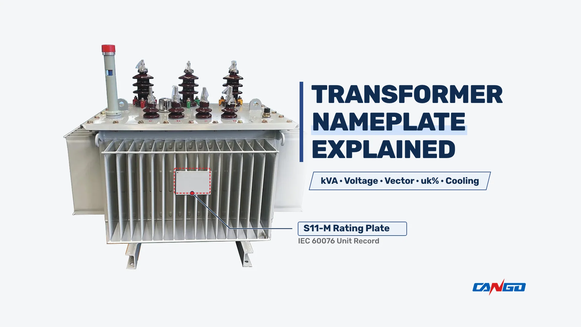
To have a transformer nameplate explained for fast site decisions, read five fields first on any rating plate: rated apparent power (kVA), rated high-voltage and low-voltage values (HV/LV), vector group, short-circuit impedance (uk%), and cooling class. Rated kVA gates continuous current capacity; HV/LV voltages gate primary feeder fit and secondary no-load voltage; the vector group gates phase displacement and neutral earthing; uk% gates secondary fault current and load voltage drop; and cooling class gates whether full kVA output requires running fans. Because the metal plate riveted to the tank or enclosure is the manufacturer’s permanent IEC 60076 record of the ratings that specific unit was built and tested to, the rating plate — not the general catalog brochure — is the technical contract at acceptance.
The Generic Example Rating Plate: Field-by-Field Reference Map
Rather than reading a plate alphabetically, group every stamped field by the engineering decision it feeds: system fit, protection and paralleling, thermal loading, and acceptance traceability.
The table below presents one complete Example plate — generic values, not a specific product. All values below (1000 kVA, 10,000 V / 400 V, 57.7 A / 1443.4 A, 50 Hz, 3 phases, Dyn11, uk = 5.0%, ONAN, and the five-position tap table) are generic format examples for arithmetic illustration, never a CANGO product record.
| Field | Example Value (Generic Example) | Where It Sits on the Plate | Decision It Feeds |
|---|---|---|---|
| Standard Reference | IEC 60076 | Header block under title | Governing rating, tolerance, and test rules |
| Serial Number & Year | EX-2026-001 / 2026 (Generic) | Header or lower-right block | Links physical unit to factory test report |
| Rated Power | 1000 kVA | Top-left main rating block | Continuous apparent power ceiling |
| Phases & Frequency | 3 Phases / 50 Hz | Top main rating block | Three-phase bus and grid frequency match |
| Rated Voltages (HV / LV) | 10,000 V / 400 V (No-Load LV) | Center-top voltage block | Feeder fit and no-load LV bus voltage |
| Rated Currents (HV / LV) | 57.7 A / 1443.4 A | Beside HV and LV voltages | HV fuse/relay and LV breaker/busbar sizing |
| Vector Group | Dyn11 | Center connection block | Parallel operation and neutral grounding |
| Impedance (uk%) | 5.0% | Center impedance block | Fault current and load voltage drop |
| Cooling Class | ONAN | Thermal block beside kVA | Natural convection vs fan-dependent kVA |
| Temperature Rise | IEC 60076-2 Limits (Oil / Winding) | Thermal block beside cooling | Permissible oil/winding rise above ambient |
| Insulation Levels | LI 75 AC 35 / AC 5 | Dielectric block | Impulse and power-frequency withstand |
| Off-Circuit Tap Table | Pos 1–5: 10,500–9,500 V to 400 V | Lower-left tap matrix | De-energized HV ratio step adjustment |
| No-Load & Load Losses | Guaranteed W at Reference Temp. | Lower-right loss block | Running-cost and test-report verification |
| Total & Oil Mass | Stamped kg (Unit-Specific) | Bottom weight row | Crane rigging, pad load, and oil pit |
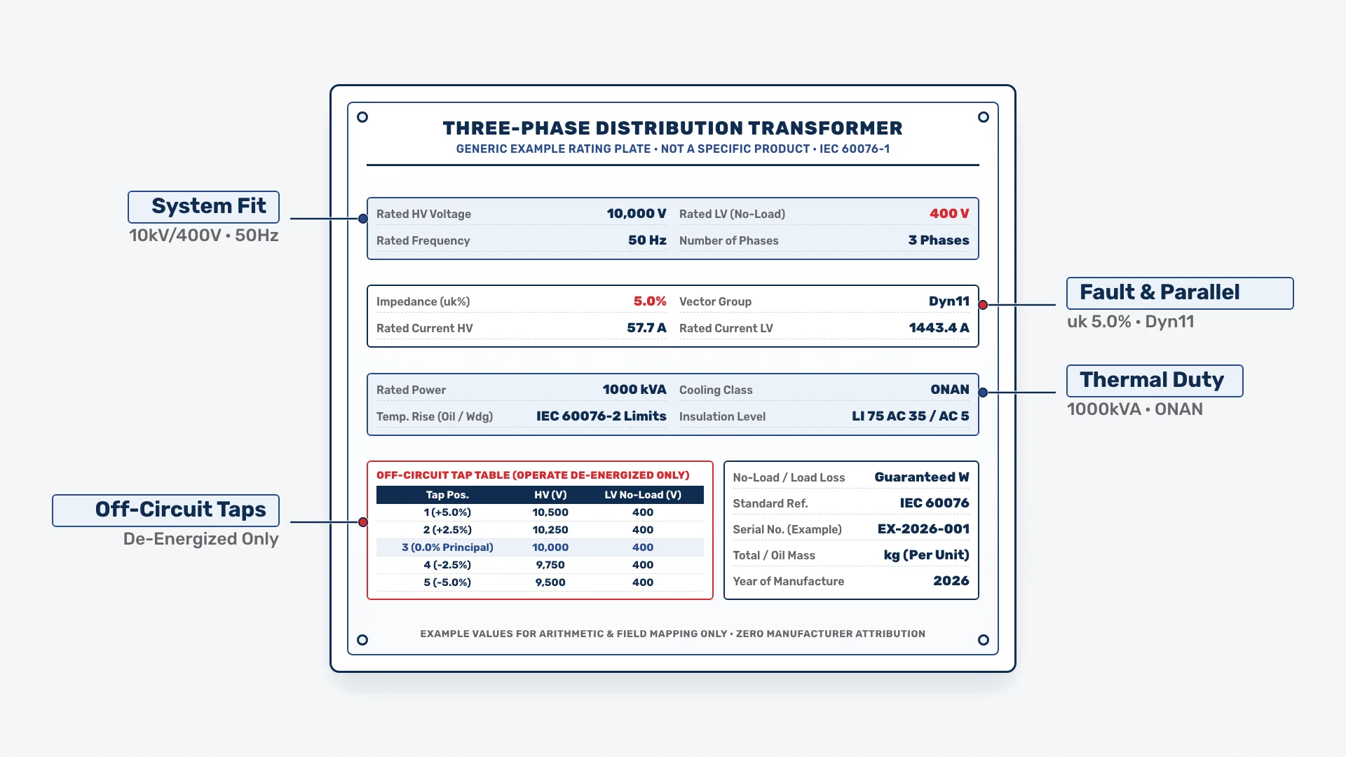
Fields That Decide Whether the Transformer Fits Your System
Four fields decide whether a unit fits your incoming feeder and low-voltage switchboard: rated voltages, frequency, phases, and the tap table.
Rated HV and LV Voltages (and the No-Load LV Rule)
- What it says: Stamps the primary HV rating (10,000 V on the generic example plate) and secondary LV rating (400 V on the generic example plate) at the principal tap.
- The decision it feeds: Confirms utility feeder match and nominal secondary bus voltage.
- What goes wrong when misread: Per IEC 60076-1, the LV voltage on the nameplate is the no-load voltage at open-circuit secondary terminals. Under load, current flowing through the winding impedance (uk%) causes terminal voltage to drop. This is the single most common nameplate misread: a buyer expecting the full 400 V example plate value at full load will “discover” a voltage problem that is actually normal regulation.
Rated Frequency (Hz)
- What it says: States the design AC frequency (50 Hz or 60 Hz).
- The decision it feeds: Confirms core flux compatibility with the grid or generator bus.
- What goes wrong when misread: Energizing a 60 Hz unit on a 50 Hz grid at rated voltage raises core flux density by roughly twenty percent, driving core saturation and overheating.
Number of Phases
- What it says: Identifies three-phase (3 Phases on the generic example plate) or single-phase construction.
- The decision it feeds: Governs busbar phasing and whether current formulas include the √3 factor.
- What goes wrong when misread: Using single-phase division (I = S / U) on a three-phase plate overstates line current by 1.732 and corrupts CT and relay settings.
Tap Changer Table (and the Off-Circuit Warning)
- What it says: Gives the HV voltage for each tap position (Positions 1 to 5: 10,500 V, 10,250 V, 10,000 V, 9,750 V, and 9,500 V on the generic example plate) against the no-load LV voltage (400 V).
- The decision it feeds: Selects the HV turn ratio step that compensates for a persistently high or low feeder voltage.
- What goes wrong when misread: You must distinguish an off-circuit (off-load) tap changer from an on-load tap changer (OLTC). In general industry practice, distribution units of the class CANGO sells normally carry off-circuit taps. Off-circuit tap changers may ONLY be operated de-energized; an OLTC is a different diverter device that operates under load. Never label an off-circuit tap changer “OLTC” — turning an off-circuit switch while energized draws an unquenched arc that can destroy the tap switch and tank.
Fields That Decide Protection and Paralleling
Four fields govern protection settings, fault breaking duty, and paralleling: rated power (kVA), rated currents (A), impedance (uk%), and vector group.
Rated Power (kVA) and Rated Currents (A)
- What they say: Rated apparent power in kVA (1000 kVA on the generic example plate) and primary/secondary line currents in amperes (57.7 A HV and 1443.4 A LV on the generic example plate).
- The decisions they feed: Rated power is in kVA, not kW, because the limit is thermal (winding current heating), independent of load power factor; for selecting capacity for a facility load, see how to size a distribution transformer in kVA. Rated currents feed HV fuse/relay settings, CT ratios, and LV breaker and busbar ampacity.
- Worked arithmetic on the generic example plate: For a three-phase unit, rated line current is derived via I = S / (√3 × U). On the Example plate — generic values, not a specific product (S = 1000 kVA = 1,000,000 VA, HV = 10,000 V, LV = 400 V):
- Example plate HV / LV currents: I_HV = 1,000,000 / (1.73205 × 10,000) = 57.7 A; I_LV = 1,000,000 / (1.73205 × 400) = 1443.4 A.
- What goes wrong when misread: Treating 1000 kVA as 1000 kW on a 0.80 power-factor motor bus pulls 1250 kVA (1804 A at 400 V), overloading the windings by 25%.
Short-Circuit Impedance (uk%) and Fault Current
- What it says: The percentage of rated voltage (5.0% on the generic example plate) that drives rated current through a short-circuited winding.
- The decisions it feeds: Sets secondary fault current, load voltage drop, and parallel load sharing. For system fault coordination, see transformer impedance and short-circuit current.
- Both opposing consequences and fault-current arithmetic: Its two consequences pull in opposite directions and must be stated together: a higher uk% produces a lower symmetrical short-circuit fault current at the secondary terminals but worse voltage regulation (a larger voltage drop under load), whereas a lower uk% delivers tighter voltage regulation under load at the cost of a higher short-circuit fault current that downstream switchgear must interrupt. Approximate fault current from the plate is Isc ≈ Irated × 100 / uk%. On the Example plate — generic values, not a specific product (Irated = 1443.4 A, uk% = 5.0%):
- Example plate LV fault current: Isc ≈ 1443.4 × 100 / 5.0 = 28,868 A ≈ 28.9 kA.
- What goes wrong when misread: Assuming a lower uk% reduces fault current leaves LV breakers underrated for fault duty, while paralleling units with mismatched uk% forces the lower-impedance unit to hog load and overheat first.
Vector Group Code Anatomy (Dyn11)
- What it says and how it decodes: In Dyn11, the capital letter is the HV winding connection (D delta, Y star, Z zigzag), the lowercase letter is the LV connection (y star, d delta, z zigzag), “n” means the neutral is brought out, and the number is the clock position of phase displacement in 30° steps (11 × 30° = 330°). For connection diagrams and harmonic behavior, see Dyn11 vs Yyn0 transformer vector groups.
- The decision it feeds and the misread: Vector group gates neutral earthing and parallel operation; paralleling mismatched vector groups (such as Dyn11 with Yyn0) drives destructive circulating fault currents across the tie breaker.
Fields That Decide How Hard You Can Run It
The thermal block governs heat dissipation, fan control requirements, and room ventilation.
Cooling Class Decode and the Dual-Rating Trap
- What it says and how it decodes: Cooling class codes decode letter by letter per IEC 60076-2: first letter = internal cooling medium (O oil, A air), second = its circulation (N natural, F forced), third = external medium (A air, W water), fourth = its circulation (N natural, F forced). ONAN means oil natural / air natural.
- The decision it feeds and the misread: A second rating such as ONAN/ONAF with two kVA values (or AN/AF on dry-type units) means the higher kVA is only available with cooling fans running. Reading only the bigger kVA number at acceptance without powering and verifying the fans is a classic error that causes thermal overload at peak load.
Temperature Rise, Insulation Class, and the Overload Boundary
- What they say and the misread: Oil-immersed plates state top-oil and average winding temperature rises tied to IEC 60076-2 limits. Dry-type plates state the insulation system class (such as Class F or Class H), whose permissible winding temperature rise is lower than the class’s temperature limit — the class letter is a temperature capability, not the allowed rise itself; see dry-type transformer temperature rise vs insulation class.
- Overload boundary: Because nameplate kVA defines continuous thermal rating at standard ambient rather than an instantaneous trip threshold, any short-term loading above rated kVA must follow the thermal limits in whether you can overload a distribution transformer.
Fields That Decide What It Costs and Whether It Is the Unit You Ordered
The commercial and dielectric fields verify efficiency, insulation coordination, and contract compliance at acceptance.
Losses and Insulation Levels (with Oil-Immersed Plate Anchor)
- Losses (no-load and load loss): No-load loss and load loss at reference temperature on the plate are guaranteed/tested values for this specific unit — they feed running-cost comparison and are checked against the test certificate at acceptance (never rely on “typical” loss figures).
- Insulation levels (LI / AC values): State the lightning impulse (LI) and power-frequency (AC) withstand voltages the unit was tested to per IEC 60076-3; misreading them risks dielectric failure or surge arrester mismatch.
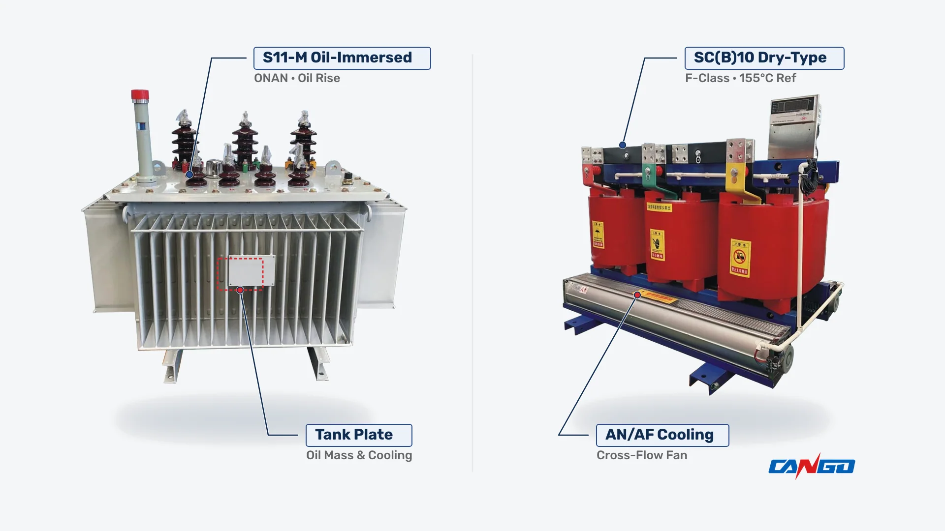
- Oil-immersed plate anchor: For the plate parameters you will actually read on a unit like this, inspect the CANGO S11-M 10kV oil-immersed transformer product page: 10 kV series from 30 to 2500 kVA (Dyn11, Yzn11, or Yyn0; HV 6, 6.3, 10, or 10.5 kV; tapping ±5% or ±2×2.5%; LV 0.4 kV; uk% of 4% for 30–500 kVA, 4.5% for 630–1600 kVA, and 5% for 2000–2500 kVA), 20 kV series from 30 to 1600 kVA (Dyn11; HV 20 kV; LV 0.4 kV; uk% of 5.5% for 30–500 kVA and 6% for 630–1600 kVA), and 0.4 / 10 / 20 kV insulation levels (1 min AC withstand 5 / 35 / 55 kV; full-wave LI 75 / 75 / 125 kV; chopped-wave 85 / 85 / 140 kV).
Traceability and the Delivery-Acceptance Checklist
The serial number, year, and standard reference (IEC 60076) tie the unit to its factory test report, and a replacement or parallel unit must be matched field by field, starting with kVA, voltages, vector group, and uk% (with its tolerance). At acceptance, check the plate, order/datasheet, and test certificate field by field:
- Serial Number & Year: Matches the factory test report identically.
- Rated kVA & Cooling Class: Nominal kVA and ONAN/ONAF (or AN/AF) match the order.
- HV/LV Voltages & Frequency: Principal HV, no-load LV, and Hz match the single-line diagram.
- Tap Table & Switch Type: Tap steps and off-circuit status match the datasheet.
- Vector Group: Symbol (Dyn11 or Yyn0) matches order and test report.
- Impedance (uk%): Test-report uk% matches the plate within IEC 60076-1 tolerance.
- Losses: Measured no-load and load losses meet order guarantees.
- Insulation Levels & Mass: LI/AC levels and masses match clearance and rigging limits.
Dry-Type Plates: What Changes
On a cast-resin dry-type unit built to IEC 60076-11, voltage, current, vector group, and uk% fields work identically to an oil-immersed plate, but three thermal fields change:
- No Oil Fields: Oil mass, liquid type, and top-oil rise disappear because windings use solid insulation.
- AN / AF Instead of ONAN / ONAF: Air is both internal and external cooling medium — AN for natural convection and AF with cooling fans running.
- Insulation Class Front and Centre: The plate states the insulation system class (such as F or H), where the class letter is a temperature capability and the permissible winding temperature rise is lower than the class limit.
For the plate parameters you will read on a dry-type unit like this, see the CANGO SC(B)10 10kV dry-type transformer product page: 6/10 kV, 20 kV, and 35 kV series from 30 to 2500 kVA (Dyn11 or Yyn0, 0.4 kV LV, tap ranges ±2.5%, ±5%, or ±2×2.5%, uk% of 4%, 6%, or 8%, load losses at the 155 °C F-class reference temperature, and 0.4 / 10 / 20 / 35 kV insulation levels with 1 min AC withstand 5 / 35 / 50 / 70 kV and LI withstand 75 / 75 / 125 / 170 kV).
Frequently Asked Questions
Is the voltage on the nameplate the voltage I will measure under load?
No. The LV voltage on a transformer nameplate is the no-load voltage at open-circuit secondary terminals. Under load, internal voltage drop across the transformer’s impedance (uk%) lowers terminal voltage below the plate value — normal regulation explained in Section 3 above.
What is the difference between the two kVA numbers on a plate with fans?
They state the passive natural-cooled rating (ONAN or AN) and the forced-air fan-cooled rating (ONAF or AF). The higher kVA rating is only available when the cooling fans are running.
Can I parallel a replacement transformer if the kVA and voltages match?
No — matching kVA and voltages is not enough. You must also verify on both nameplates that the vector group matches identically and that short-circuit impedance (uk%) is within IEC 60076-1 tolerance.
What does Dyn11 on the plate actually tell me?
It gives the HV delta connection (D), LV star connection (y), brought-out neutral (n), and 30° clock-hour phase displacement (11 × 30° = 330°) in one code; the full decode is linked in Section 4 above.
The plate is damaged or missing. What now?
Do not guess ratings or energize an unidentified unit on assumed values. Use the stamped serial number and substation records to retrieve the original factory test report from the manufacturer before energizing.
Sources
- IEC 60076-1:2011, Power transformers — Part 1: General (IEC Webstore) — Rating plate markings, tappings, vector groups, and tolerances.
- IEC 60076-2:2011, Power transformers — Part 2: Temperature rise for liquid-immersed transformers (IEC Webstore) — Cooling codes (ONAN, ONAF) and oil/winding rise limits.
- IEC 60076-3:2013, Power transformers — Part 3: Insulation levels, dielectric tests and external clearances in air (IEC Webstore) — Rated LI and AC withstand levels.
- IEC 60076-5:2006, Power transformers — Part 5: Ability to withstand short circuit (IEC Webstore) — Short-circuit withstand and symmetrical fault current from uk%.
- IEC 60076-11:2018, Power transformers — Part 11: Dry-type transformers (IEC Webstore) — Dry-type rating plates, AN/AF cooling, and insulation classes.
- CANGO Product Page, S11-M 10kV Oil-Immersed Transformer (cangopower.com/product/s11-m-10kv-oil-immersed-transformer/) — 10/20 kV series ratings, vector groups, tap ranges, uk%, and insulation levels.
- CANGO Product Page, SC(B)10 10kV Dry-Type Transformer (cangopower.com/product/scb10-10kv-dry-type-transformer/) — 6/10/20/35 kV dry-type series ratings, 155 °C F-class loss reference, uk%, and insulation levels.