LV switchgear busbar sizing needs three linked checks: continuous-current performance inside the actual enclosure, short-circuit duty, and the mechanical/joint arrangement covered by the design evidence. Copper cross-section is one input to those checks. It is not an assembly current rating.
For a project buyer, the useful output is a busbar schedule that identifies material, bar arrangement, loading, temperature-rise evidence, fault ratings and protection conditions. A statement such as “1,600 A busbar” or “50 kA board” leaves important conditions unresolved.
Before accepting a proposal:
- Confirm the loading and service conditions used for temperature-rise verification.
- Separate Icw with its duration, Ipk, and any conditional Icc tied to a specified protective device.
- Match the actual bars, joints, supports and enclosure to the applicable verified arrangement.
Turn the system requirements into a busbar schedule
Start with the single-line diagram and permitted operating configurations. Record how sources, bus sections, couplers and outgoing circuits can be loaded together. Do not assume that every outgoing breaker rating can simply be added to obtain the required assembly current.
IEC 61439-1:2020 provides the general assembly framework and introduced group rated current into its updated temperature-rise approach. It is used with the relevant product part; IEC 61439-2:2020 covers power switchgear and controlgear assemblies. Their public scope and revision information establish that framework, without qualifying any particular CANGO design. IEC 61439-1 publication information, IEC 61439-2 publication information
| Project input | Put into the busbar review | Evidence or confirmation needed |
|---|---|---|
| Supply and operating scheme | Voltage, frequency, source combinations, bus sections and coupler duty | Agreed single-line diagram and loading cases |
| Continuous loading | Required assembly, main/distribution bus and circuit duties | Declared ratings with the relevant simultaneous loading basis |
| Service conditions | Ambient temperature, enclosure, ventilation, installation and altitude | Temperature-rise verification applicable to those conditions |
| Fault study | Prospective RMS fault current, peak and clearing/withstand requirements | Applicable assembly short-circuit schedule |
| Protective arrangement | Exact device, voltage, trip unit/settings or fuse designation | Confirmed protective combination and limitation data where relied upon |
| Conductors and construction | Material, width, thickness, number, orientation, joints and supports | Configuration drawing and applicability of verification evidence |
| Neutral and protective circuits | Earthing arrangement, unbalance and harmonic duty | Separate N/PEN/PE requirements and construction basis |
Use the LV switchgear planning guide for the wider inquiry information. Here, the decision is whether the proposed busbar arrangement meets those inputs.
Use cross-section to describe the candidate, then verify its current duty
For rectangular bars, the total conductor area per phase is:
A = n × width × thickness
where n is the number of parallel bars assigned to that phase. As a hypothetical comparison:
| Assumed arrangement | Area calculation | Total copper area per phase |
|---|---|---|
| One 100 × 10 mm bar | 1 × 100 × 10 | 1,000 mm² |
| Two 50 × 10 mm bars | 2 × 50 × 10 | 1,000 mm² |
At an assumed 1,600 A, both produce the same arithmetic current density:
J = I / A = 1,600 / 1,000 = 1.6 A/mm²
This does not establish that either arrangement can carry 1,600 A inside a proposed cabinet. The two arrangements differ in exposed surfaces, mutual heating, AC current distribution, orientation and connection geometry. Their thermal and mechanical performance must be assessed as arrangements, not inferred from equal area.
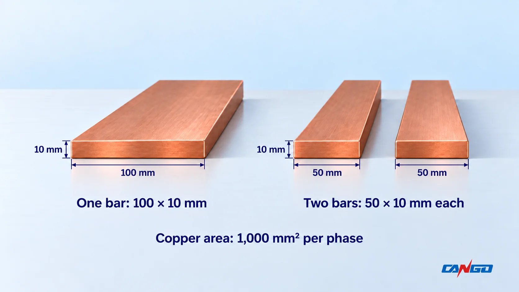
The Copper Development Association and European Copper Institute’s Copper for Busbars explains the heat balance, conductor resistance, skin/proximity effects and arrangement factors behind this distinction. A free-air table or approximate current-density starting point cannot qualify an enclosed assembly. Chapman and Norris, Copper for Busbars
Material must also be explicit. A copper area is not automatically an equivalent aluminium area. Conductivity, temperature, joints, mechanical properties and the actual design basis need review when material changes.
Verify temperature rise with the complete assembly in view
The relevant question is whether the offered arrangement stays within its applicable temperature limits under the specified loading and service conditions. That includes the bars, joints, connected equipment, insulation/support materials and the air inside the enclosure.
Record the bar orientation and spacing, ventilation, enclosure size/protection, compartment boundaries, nearby heat-producing devices and connection arrangement. Changing one can affect the thermal conditions of another. Adding copper without checking the enclosure and interfaces does not close the verification task.
BEAMA’s July 2023 verification guide, written for BS EN IEC 61439-2:2021, explains temperature-rise verification of PSC assemblies and the conditions attached to supported test, comparison and calculation routes. That national adoption corresponds to the 2020 IEC framework. Do not treat the existence of a calculation method as permission to apply it to any arrangement. Request the manufacturer’s applicable method, reference design and conditions. BEAMA Guide to Verification
Keep neutral and protective-circuit requirements in the schedule. Unbalanced and harmonic-rich loads require their own assessment; do not reduce the neutral merely because a simplified three-phase load calculation looks balanced. Likewise, a phase-busbar selection does not determine the PE/PEN construction by itself.
Separate Icw, Ipk and conditional Icc
Use distinct fields when reviewing an assembly’s fault capability:
| Quantity | What the buyer must establish | Common incomplete substitute |
|---|---|---|
| Icw | Rated RMS short-time withstand current and corresponding duration | A kA value with no time |
| Ipk | Rated peak withstand current applicable to the arrangement | Assuming a universal multiplier from RMS current |
| Icc, where declared | Prospective short-circuit rating under the specified protective arrangement and conditions | Assuming any upstream breaker gives the same protection |
| Breaker Icu/Ics | The selected breaker’s applicable breaking duties | Treating component breaking capacity as the assembly busbar rating |
IEC’s public Part 1 preview lists these assembly current characteristics separately. BEAMA’s verification guidance addresses short-circuit evidence for the complete PSC assembly, including busbars, interconnections and mountings. Breaker documentation alone cannot establish that complete construction. IEC 61439-1 publication and preview information, BEAMA verification guide, short-circuit section
Supports, joints and phase arrangement remain part of the selection
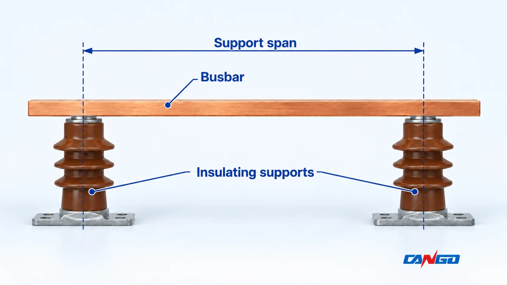
Fault currents produce forces as well as heating. In an ideal two-conductor model with fixed geometry and equal instantaneous current magnitudes, force magnitude grows with current squared and inversely with separation. An actual three-phase assembly also involves phase timing, asymmetry, bar orientation, stiffness, fixity and dynamic response. The ideal relation explains sensitivity; it is not a cabinet support calculation.
Request support material, span, mounting strength, conductor orientation and the actual joint design. A larger copper section alone does not establish an allowable support span. Joints also have contact/spreading resistance; use the manufacturer’s verified construction and instructions rather than a generic bolt-torque value. Copper for Busbars, short-circuit and joint guidance
Worked screen: a 1,600 A proposal with a stated fault duty
Assume the project requires 1,600 A at the agreed service conditions. Its fault study requires 36 kA RMS for 0.4 s and 80 kA peak at the assembly location. Assume a supplier proposes a construction declared for 50 kA for 1 s and 105 kA peak, with two 50 × 10 mm copper bars per phase. Every value in this example is hypothetical, not a CANGO rating or test result.
| Check | Example comparison | What can be concluded |
|---|---|---|
| Copper area | 2 × 50 × 10 = 1,000 mm² per phase | Describes the candidate; does not prove 1,600 A ampacity |
| Current density | 1,600 / 1,000 = 1.6 A/mm² | Arithmetic only; thermal verification remains required |
| RMS magnitude and duration | 36 kA / 0.4 s versus declared 50 kA / 1 s | Preliminary comparison fits the stated magnitude/time envelope, subject to evidence applicability |
| Peak | Required 80 kA versus declared 105 kA | Preliminary peak screen only; supports and construction must match the declaration |
| Temperature and protection basis | Not established by the numerical comparisons | Remain open until the loading, enclosure and protective arrangement are confirmed |
For an explicitly simplified constant-RMS heating comparison:
Required exposure proxy = 36² × 0.4 = 518.4 kA²s
Declared-duty proxy = 50² × 1 = 2,500 kA²s
Ratio = 518.4 / 2,500 ≈ 0.207
The ratio does not grant a new current rating. It leaves waveform/DC-offset effects, starting temperature, conductor/support limits, fault location and design applicability unresolved. Do not extend or convert a declared rating to a higher current or different duration without the manufacturer’s applicable verification basis and peak/other conditions.
The practical result is a list of open evidence items, not approval of two 50 × 10 mm bars. The geometry, neutral/protective circuits, joint construction, temperature-rise basis and fault-duty declaration still need to agree across the offer and drawings.
If protection limits the fault, preserve the exact combination
A conditional assembly rating may rely on a specified short-circuit protective device. Record its make/type, frame or fuse designation, operating voltage, relevant current range and settings, plus the applicable mounting and connection conditions.
When relying on current limitation, review both total let-through I²t and peak cut-off current at the relevant prospective fault conditions. A nominal time delay or a high Icu marking does not provide those two quantities. For a current-limited waveform, use the applicable manufacturer data; do not substitute prospective RMS current squared times the nominal delay.
BEAMA identifies protective-device limitation and construction conditions when discussing reference-design comparison and substitution. Replacing a device with another carrying the same current rating therefore requires a documented applicability review. BEAMA Guide to Verification
Also check any intentional protection delay used for selectivity against the assembly duty. The protective device and the assembly must be evaluated together rather than selecting each from unrelated maximum ratings.
What to request for a CANGO LV busbar review
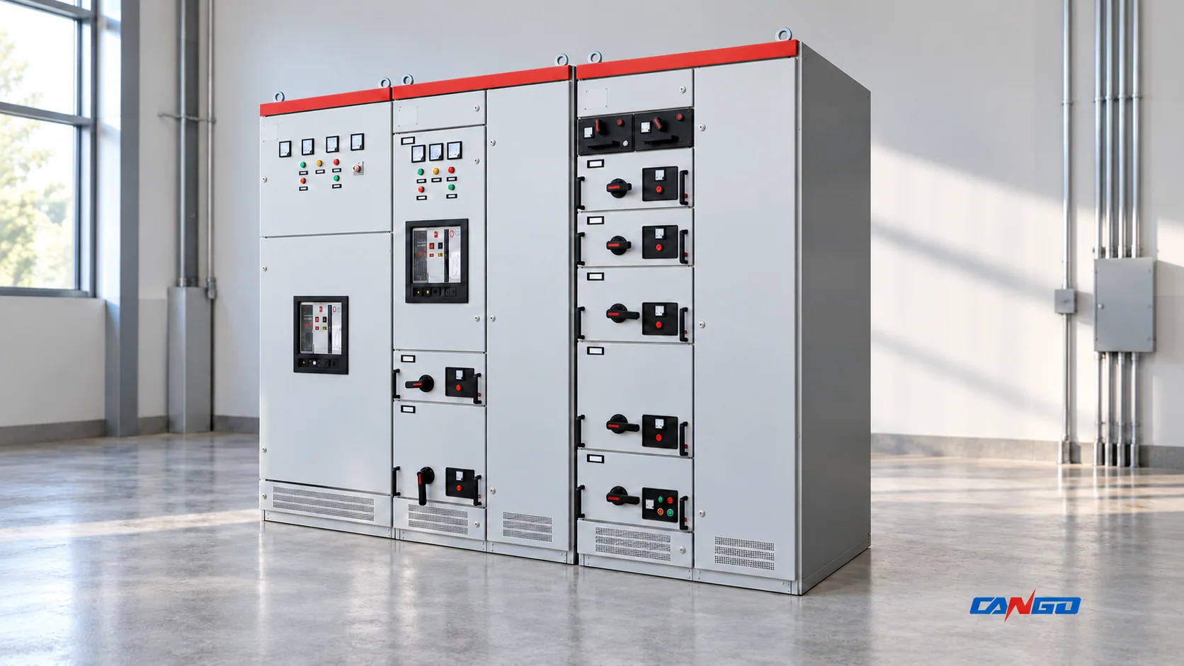
CANGO’s GGD, GCS and MNS pages provide fixed/withdrawable equipment routes and project inquiry information. A family table does not specify the final copper sections, support spacing or verification scope for every ordered panel.
Submit one coordinated package:
- Single-line diagram, permitted source/coupler configurations and load schedule.
- Required assembly/main/distribution/circuit currents, loading groups and service conditions.
- RMS fault current, required duration, peak and protection-clearing/limitation basis.
- Proposed conductor material, section, parallel arrangement, joints, supports and enclosure drawing.
- Neutral, PE/PEN, harmonic and unbalance requirements.
- Exact protective-device and setting information wherever a conditional rating or limitation is relied upon.
- Configuration-specific temperature-rise and short-circuit evidence, its reference design and any deviations.
Use the design versus routine verification guide to organize the evidence review. Changes in enclosure/separation, bars, supports, joints or protection need an applicability decision; a routine record is not a substitute for that design assessment.
Send the project schedule and drawings to CANGO for an offered-configuration discussion. The review should close the required current, temperature, fault and construction fields before the busbar arrangement is accepted.
References
- IEC — IEC 61439-1:2020, general rules; public scope, edition and preview information, incorporating published corrigenda.
- IEC — IEC 61439-2:2020, PSC assembly requirements; public scope and edition information.
- David Chapman and Toby Norris / Copper Development Association / European Copper Institute — Copper for Busbars, revised May 2014; physical engineering guidance, not a source of current IEC acceptance limits.
- BEAMA — Guide to Verification: Low-voltage Power Switchgear and Controlgear Assemblies in Accordance with BS EN IEC 61439-2:2021, July 2023.
- CANGO — GGD, GCS and MNS product information, checked 1 November 2026; product routes and exterior references.