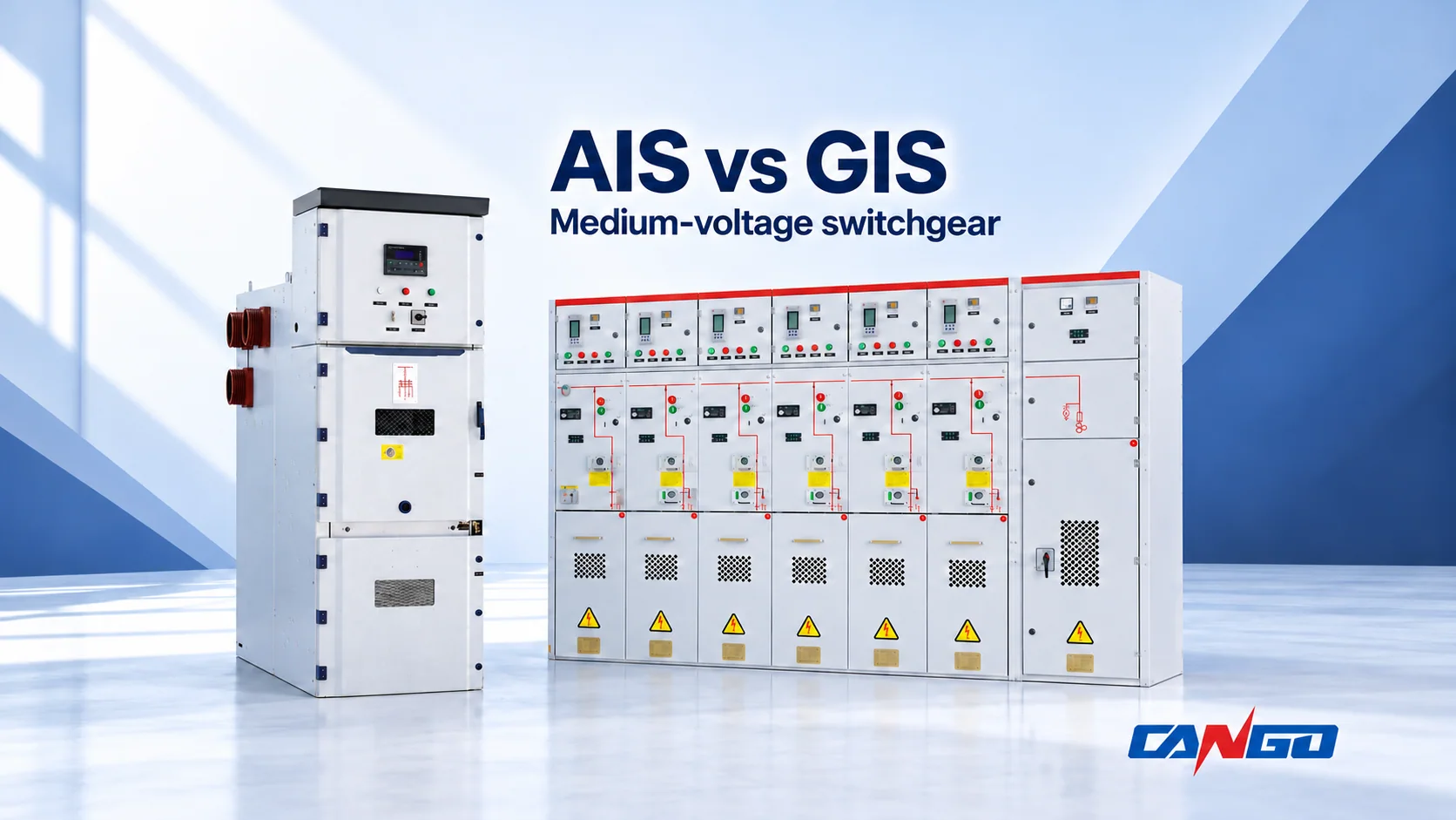
Choose air-insulated switchgear (AIS) when a suitable lineup fits the site and its access, maintenance and expansion arrangements match the operating plan. Investigate gas-insulated switchgear (GIS) when a compact, controlled primary-insulation enclosure resolves a significant space or exposure constraint, and the proposed gas technology and service arrangements are acceptable.
For a medium-voltage project, the useful comparison is the same electrical job in the same installation conditions. A smaller cabinet or a lower equipment price does not settle the decision. Match the feeder functions, fault duties and operating requirements first; then compare installed space, restoration and lifecycle cost.
AIS vs GIS: the differences that affect selection
The table compares conventional atmospheric-air AIS with equipment using a controlled gas compartment. Modern solid-insulated and hybrid designs need their own description; a supplier label alone is insufficient.
| Comparison point | AIS | GIS | What the buyer should request |
|---|---|---|---|
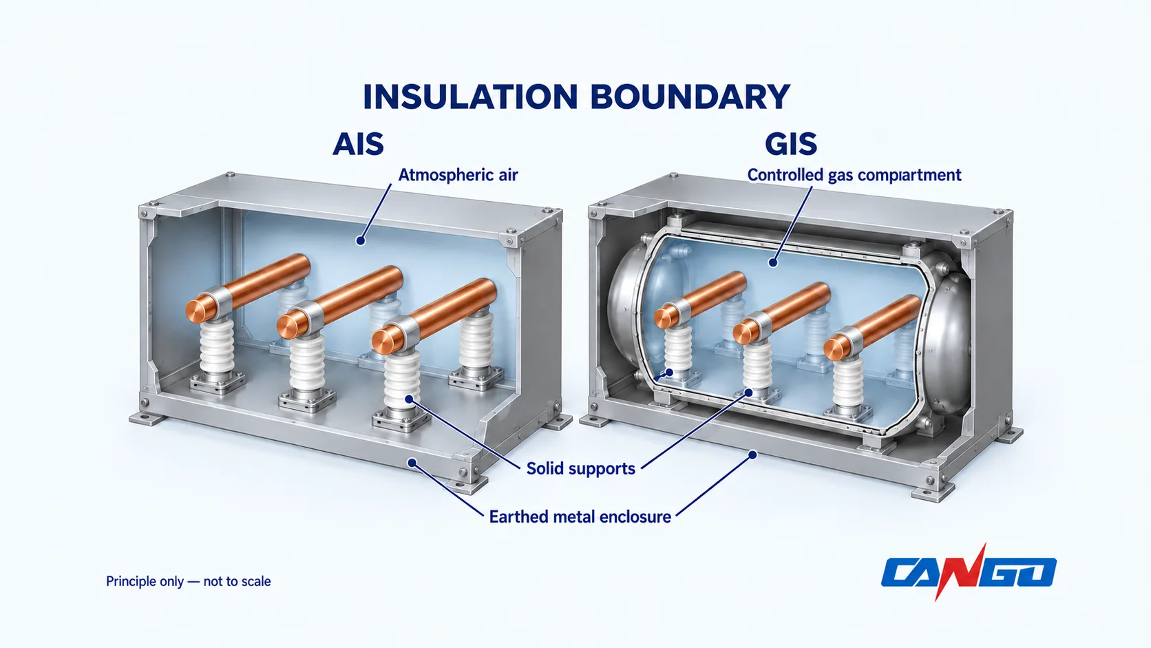
| Main insulation boundary | Atmospheric air forms part of the insulation system, alongside solid supports and barriers | Specified primary parts are enclosed in a controlled gas compartment | Insulation-medium declaration and compartment arrangement |
| Equipment envelope | Air clearances influence the cabinet arrangement | Gas insulation can support a compact arrangement | Drawings for equivalent duties and the same number of functional ways |
| Site exposure | Room conditions and enclosure design matter to the air-insulated parts | Sealed primary compartments change the exposure boundary | Declared service conditions for the complete assembly and its interfaces |
| Maintenance and restoration | Access and replaceable assemblies depend on the design | Service scope depends on gas compartments and replaceable modules | Maintenance instructions, fault-restoration method and spare strategy |
| Extension | Busbar interfaces, space and outages must be planned | Module compatibility and gas-compartment interfaces must be planned | Ultimate lineup and documented extension procedure |
| Gas obligations | The AIS label does not identify every component medium | The GIS label does not establish gas composition or legal acceptance | Insulation and breaking media, destination-market acceptance and end-of-life scope |
The Commission-hosted technical briefing on SF6 and alternatives, section 2.2, distinguishes insulation from interruption and describes the footprint and exposure trade-off. Its 2020 market observations should not be treated as current product availability or a fixed space-saving ratio.
For the wider ratings and equipment map, start with the medium-voltage switchgear selection guide.
What AIS and GIS actually describe
AIS and GIS describe an insulation architecture. They do not, by themselves, specify the breaker, protection arrangement, enclosure classification or network topology.
In conventional MV AIS, insulation paths include the surrounding atmospheric air. In GIS, a controlled gas compartment provides a different primary-insulation boundary. Both can be metal-enclosed. The Ecofys/ETH study commissioned by Germany’s environment ministry, sections 4.1–4.3, explains these boundaries. Solid supports and interfaces remain part of the insulation design in either case.
Insulation is a separate choice from interruption
A vacuum circuit breaker can be used within air-insulated or gas-insulated equipment. The vacuum interrupter describes where current interruption occurs; it does not identify the insulating medium around the complete primary circuit. Equally, calling equipment AIS does not prove that every component is free of fluorinated gases.
Ask for two separate declarations: what insulates the primary parts, and what interrupts the current? A third declaration should identify the actual switching duty: circuit-breaker protection, load switching, switch-fuse protection or another function. These distinctions appear in the Commission briefing’s insulation/breaking-medium comparison.
An RMU, or ring main unit, describes a functional arrangement used in distribution. It is not a synonym for GIS. Do not compare a secondary-distribution RMU and a primary breaker lineup as interchangeable equipment simply because both carry the same voltage-class label.
Compare complete installation space
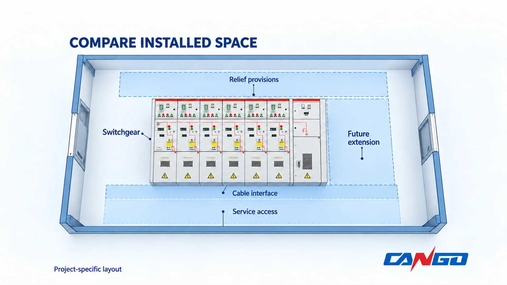
GIS can be attractive when the equipment envelope is a binding constraint. However, a compact enclosure still needs a workable installation around it. Compare the proposed room and interfaces, including:
- The complete incoming, outgoing, metering and bus-section arrangement.
- Operating and maintenance access, including removal of any replaceable assembly.
- Cable terminations, bending space and the available cable-entry route.
- Pressure-relief or exhaust provisions required by the offered installation design.
- Transport, door openings, lifting and eventual replacement access.
- Space and connection provisions for the intended final extension.
Request the same scope from both bidders. One drawing may include a metering panel and future bay while the other shows only switching modules. Comparing their cabinet widths would reward an incomplete scope.
Use the supplier’s installation drawing to test whether the offer fits the actual room. Do not create a project allowance by applying a generic percentage reduction to an AIS layout. Equipment footprint, installed footprint and building cost are different quantities.
Match site exposure to the insulation boundary
Dust, moisture, condensation, salt, temperature and altitude belong in the inquiry before an insulation architecture is chosen. A controlled gas compartment can reduce exposure of its enclosed primary parts to the surrounding atmosphere. That benefit does not automatically extend to every cable termination, operating mechanism, relay or auxiliary circuit.
The UBA-hosted study’s discussion of enclosed insulation distinguishes the primary compartment from atmospheric-air arrangements. For procurement, carry that distinction through to the whole assembly: ask which interfaces remain exposed and what environmental controls they require.
For an indoor industrial room with manageable conditions and sufficient space, review AIS against the owner’s access and servicing needs. For a constrained distribution location with difficult exposure, evaluate whether a sealed-primary design addresses the actual problem. Confirm the offered ambient, condensation, corrosion and altitude conditions in both cases. A robust-looking enclosure is not evidence of an ingress rating or site suitability.
Compare maintenance, fault restoration and expansion
Low maintenance is useful only when the supplier defines its scope. It should not be read as a promise that the complete switchboard needs no attention.
The UK Health and Safety Executive’s Electrical switchgear and safety guidance specifically explains that equipment described as low maintenance still requires maintenance. Its guidance ties the maintenance decision to equipment type, manufacturer instructions, age, operating frequency and service history.
Compare three different operating questions:
- Routine service: Which mechanisms, auxiliary circuits, interfaces and condition indicators require attention, and under what manufacturer instructions?
- Fault restoration: If a breaker, cable termination or sealed primary module is damaged, what must be isolated, replaced and tested before return to service?
- Future extension: Can the intended bay be added using documented interfaces, and what outage, specialist work and parts are required?
Obtain a written boundary for work the owner’s qualified team can perform and work requiring manufacturer or specialist support. Request the replaceable-item list, handling requirements and spare availability. Do not assume that a withdrawable breaker makes every fault easy to repair, or that a sealed module will be recoverable within the owner’s outage window.
Expansion compatibility also needs evidence. A matching voltage or similar cabinet face does not establish interchangeable busbar connections, modules, protection interfaces or parts. The HSE guidance treats spares and the condition of retained equipment as consequential replacement considerations.
Verify the gas before accepting the offer
GIS does not automatically mean SF6, and SF6-free does not automatically mean that equipment contains no fluorinated greenhouse gas. Request the actual insulation and breaking media, the applicable documentation and the destination-market acceptance basis.
For EU projects, the European Commission’s switchgear F-gas FAQ, version 3 dated 19 November 2025, explains the general restrictions under Regulation (EU) 2024/573:
| MV primary or secondary distribution equipment | General restriction on putting into operation, subject to derogations |
|---|---|
| Rated voltage up to and including 24 kV | No F-gas in the insulation or breaking medium from 1 January 2026 |
| Rated voltage above 24 kV and up to and including 52 kV | No F-gas in the insulation or breaking medium from 1 January 2030 |
These are EU-specific commissioning restrictions with defined exceptions. They do not mean every existing GIS installation must immediately be replaced. Procurement timing, extension or repair scope, and any derogation need a project-specific review. The FAQ is explanatory; the regulation remains the legal authority.
For a project being commissioned in 2026, gas acceptability can therefore eliminate an option before footprint or price is compared. Obtain written confirmation for the offered configuration rather than relying on an insulation-family name.
Which architecture fits the project?
Use the following as directions for investigation, then require the proposed equipment to meet the common specification.
| Project condition | Direction to investigate | What could change the preference |
|---|---|---|
| Industrial room with adequate space and an established service strategy | AIS with access and replaceable assemblies suited to the operating plan | Exposure controls, fault duty or the final layout may make that arrangement unsuitable |
| Compact urban station or another location where available space limits the scheme | GIS or another compact enclosed-insulation design | Cable interfaces, relief provisions or replacement access may remove the apparent space advantage |
| Contamination or condensation is difficult to control | Assess a sealed-primary design and its remaining exposed interfaces | The complete assembly still needs suitable environmental conditions |
| Outage duration is tightly constrained | Compare isolation and restoration arrangements in both architectures | Spare availability, module replacement and specialist mobilisation may dominate the choice |
| Several future extensions are expected | Compare the ultimate lineup and documented extension arrangements | Compatibility and outage requirements can outweigh the initial footprint |
| Destination-market rules exclude the proposed gas | Investigate an acceptable AIS, gas or solid-insulated alternative | Architecture labels do not prove compliance; verify the exact offered media and assembly |
A preference becomes defensible when a specific constraint is resolved. If neither alternative meets the required duty, service conditions or regulatory basis, revise the offered design rather than selecting the less unsuitable quotation.
Make AIS and GIS quotations comparable
Keep the comparison inside the applicable standards framework. The official scope of IEC 62271-200:2021+AMD1:2024 covers AC metal-enclosed assemblies above 1 kV through 52 kV, including air-insulated and/or fluid-filled compartments. It is not a certificate for an individual product.
Specify required continuity, partition and internal-arc classifications separately where applicable. Neither AIS nor GIS, by itself, establishes them. The metal-clad versus metal-enclosed guide explains the terminology and evidence boundaries.
| Common comparison schedule | Information required from both offers |
|---|---|
| Electrical job | Same single-line diagram, number of ways, switching/protection functions, metering and control interfaces |
| Electrical duty | System/rated voltage, insulation level, frequency, normal current, short-circuit duties and protection basis |
| Offered construction | Compartment arrangement, insulation and interruption media, required classifications and applicable verification documents |
| Installation | Complete layout, cable interfaces, access, relief provisions, environment and final extension arrangement |
| Operating support | Maintenance scope, isolation boundaries, replaceable items, spare strategy, specialist support and restoration method |
| Commercial scope | Equipment, transport, installation interfaces, commissioning support, planned service, gas obligations and end-of-life work |
Compare cost over one declared ownership period and the same scope. Use actual quotations and maintenance proposals; include outage exposure as an explicit scenario rather than inventing a universal failure rate. A lower equipment price may be offset by building work, while a smaller lineup may bring different service or replacement costs. Neither outcome is guaranteed by its insulation medium.
The MV switchgear quotation checklist can help assemble the common inquiry package.
Review the relevant CANGO product routes
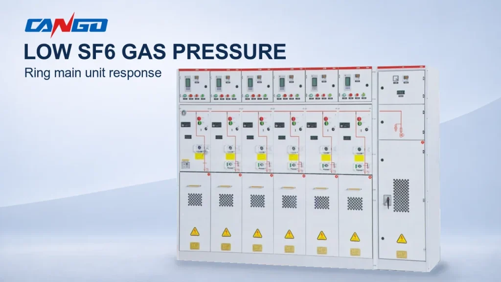
CANGO’s KYN28-12 withdrawable metal-enclosed switchgear is a starting route for projects requiring that lineup construction. The SRM-12 gas-insulated RMU is a different route for a modular ring-network or terminal distribution arrangement. Their published descriptions do not establish equivalent feeder functions, ratings or service arrangements.
Where the binary AIS/GIS choice does not fit the requirement, CANGO also lists the GTXGN-12 solid-insulated RMU, described with epoxy-resin insulation and vacuum switching. Review it as a distinct design, with its own configuration and evidence requirements.
Use the CANGO medium-voltage product range to identify candidate families. For a configuration review, send CANGO the single-line diagram and project requirements, including the electrical duty, destination and commissioning date, room layout, environment, maintenance policy and future extension. Request the insulation declaration, actual gas where applicable, offered classifications and supporting documents for that specific proposal.
References
- Burges, K.; Warncke, K.; Gschrey, B. — Briefing paper: SF6 and alternatives in electrical switchgear and related equipment, March 2020, section 2.2; technical assessment hosted by the European Commission.
- Ecofys and ETH Zurich — Concept for SF6-free transmission and distribution of electrical energy, 28 February 2018, sections 4.1–4.3; government-commissioned technical research hosted by Germany’s Umweltbundesamt.
- UK Health and Safety Executive — Electrical switchgear and safety, INDG372; maintenance and replacement guidance.
- European Commission — FAQ on switchgear as regulated by the F-gas Regulation (EU) 2024/573, version 3, 19 November 2025, Q2–Q5 and Table 1; explanatory guidance.
- IEC — IEC 62271-200:2021+AMD1:2024 CSV, official scope and consolidated-edition listing.
- CANGO product information — KYN28-12, SRM-12 and GTXGN-12, product summaries and configuration information checked 25 October 2026.