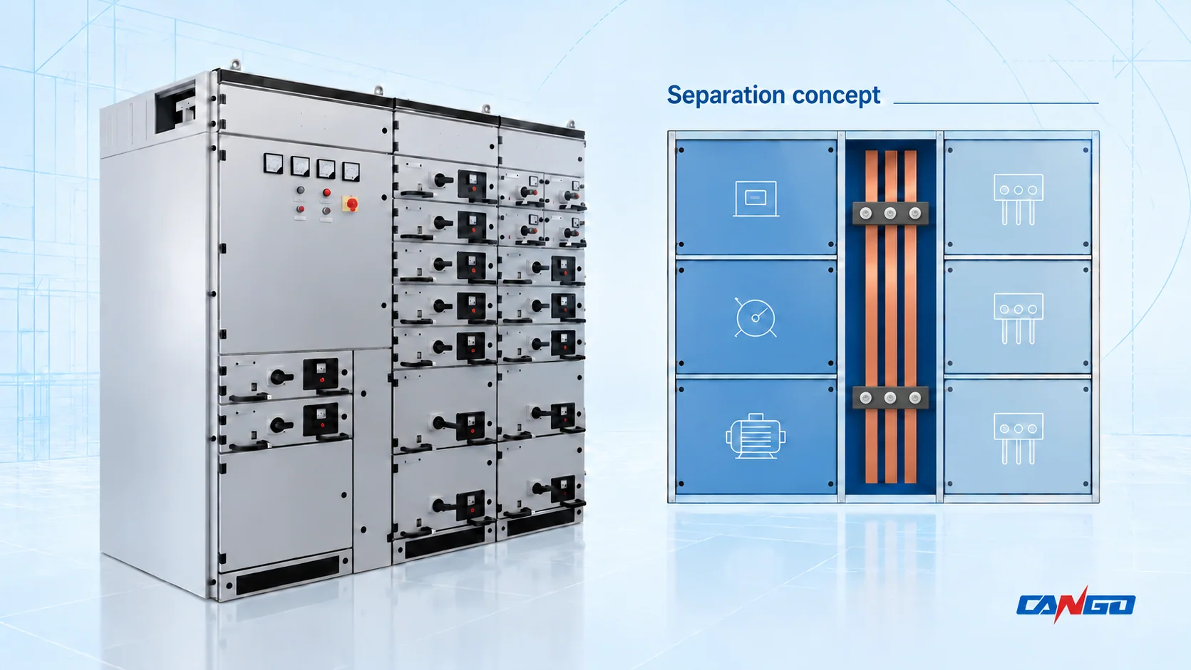
Form 2 separates busbars from functional units. Form 3 also separates the functional units from one another, while their cable terminals can occupy a common terminal space. Form 4 additionally separates each circuit’s terminal group from other circuit terminal groups and the busbars.
The suffix matters: 2a/2b and 3a/3b distinguish whether the terminals are separated from the busbars. For 4a/4b, the distinction is whether terminals sit inside or outside their associated functional-unit compartment.
Choose the complete form around the access tasks your project needs, then check the offered compartment drawings. A form number alone does not establish internal-arc performance, guarantee uninterrupted supply, or authorize work on energized equipment.
What is separated inside a low-voltage assembly?
Three objects determine the comparison:
- Busbars distribute power through the assembly, including its distribution busbars.
- Functional units are the devices and associated parts performing a circuit function, such as an outgoing feeder or motor starter.
- Terminals are the connection points for external conductors. A circuit’s terminal group must be distinguished from the terminals serving other circuits.
A door or drawer does not, by itself, define a functional separation boundary. The arrangement behind it, including barriers and protected spaces, determines the declared form.
IEC 61439-1:2020 establishes the general assembly requirements and verification framework. For power switchgear and controlgear assemblies, it is used with IEC 61439-2:2020. The separation form is one characteristic to agree for the proposed assembly; it does not replace its electrical ratings or verification.
Form 2a, 2b, 3a, 3b, 4a and 4b compared
Every form below separates busbars from the functional units. The additional boundaries differ.
| Form | Units separated from one another? | Terminals separated from busbars? | Terminal arrangement |
|---|---|---|---|
| 2a | Not required | Not required | No requirement for an individual terminal space for each circuit |
| 2b | Not required | Yes | No requirement for an individual terminal space for each circuit |
| 3a | Yes | Not required | Terminals separate from functional units; circuit terminal groups may share a space |
| 3b | Yes | Yes | Terminals separate from functional units; circuit terminal groups may share a space |
| 4a | Yes | Yes | Each circuit’s terminals share its unit compartment; terminal groups are separated from other circuit groups |
| 4b | Yes | Yes | Each circuit’s terminals have a separate enclosed space outside its unit compartment |
“Not required” identifies a boundary the stated form does not demand. It is not a claim that every supplier implements that form identically. These distinctions are summarized in ABB’s IEC 61439 workbook, printed page 52.
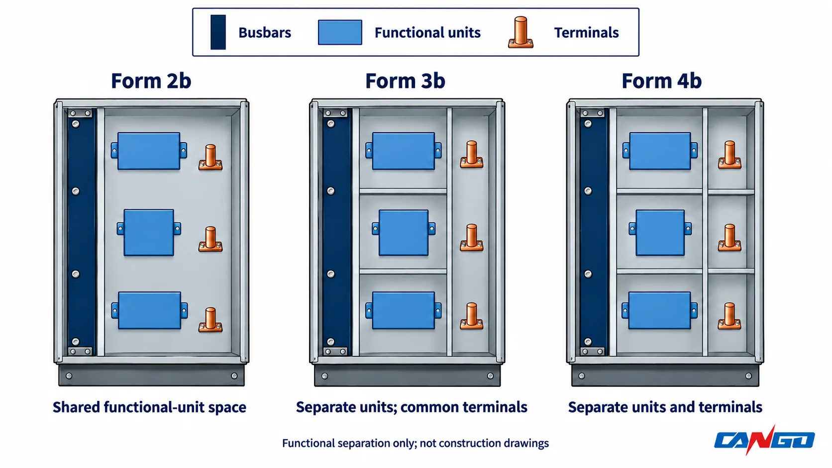
The a/b suffix changes meaning at Form 4
For Forms 2 and 3, ask: are the external-cable terminals separated from the busbars? The b variant requires that boundary. Schneider Electric’s Form 2a/2b explanation confirms this distinction.
For Form 4, ask: where are the terminals relative to their own functional unit? Form 4a keeps them together; Form 4b puts the terminals outside that unit’s compartment. Both arrangements segregate one circuit’s terminal group from other circuit terminal groups and busbars. ABB’s assembly construction guide, chapter 6, illustrates these boundaries.
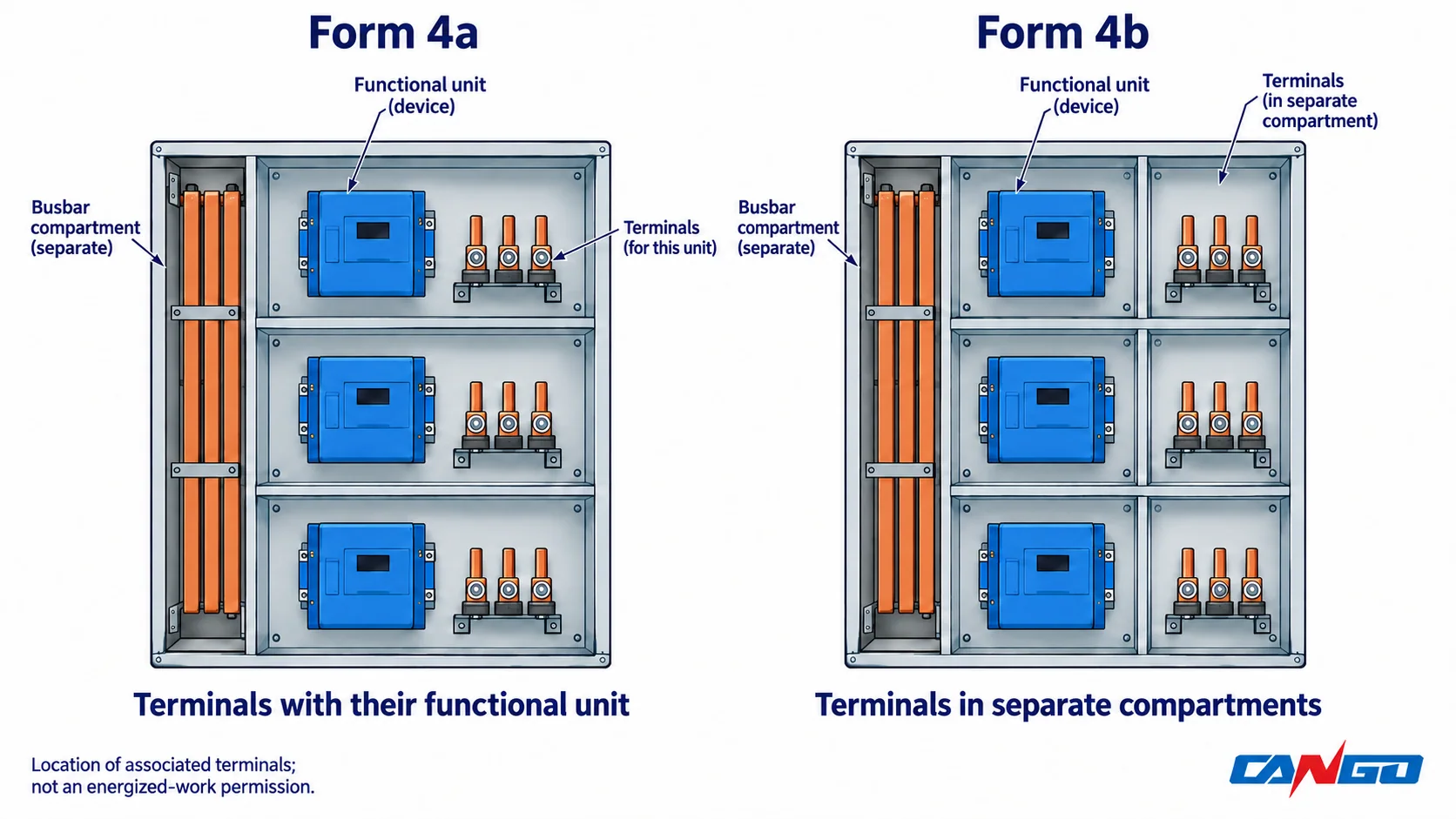
Review external-conductor paths and neutral connections as well as the device terminals. The form does not automatically mean individual phase-by-phase cable compartments. A tender requiring further cable segregation must describe it explicitly.
Choose the form from the access task
Start by writing down what personnel need to access and which other circuits must remain available. “High reliability” is too vague to establish those boundaries.
The following is a specification shortlist, not an IEC rule assigning forms to particular industries.
| Project access requirement | Form to examine | Decision that still needs confirmation |
|---|---|---|
| Whole-board shutdown is acceptable; busbars need separation from the units | Form 2a or 2b | Whether terminals need their own busbar boundary; actual access and isolation arrangement |
| Individual units need defined boundaries; a common terminal space is acceptable | Form 3a or 3b | Terminal-to-busbar boundary and what is exposed when a unit or terminal cover is opened |
| Each circuit and its terminals need to remain within an individual circuit compartment | Form 4a | Access to the unit and its associated terminals within the same compartment |
| Each circuit’s terminals need a separate access space outside its unit compartment | Form 4b | Individual terminal enclosures, cover boundaries and cable-entry arrangement |
For example, a maintenance plan focused on inspecting an isolated feeder unit presents a different question from a future project that needs access to that feeder’s cable terminals. Form 3b can address the first boundary distinction while still retaining a common terminal area. A requirement for circuit-by-circuit terminal separation brings Form 4 into the discussion.
That comparison does not promise that other circuits can remain energized during either task. The manufacturer’s instructions, actual isolation provisions, risk assessment and local requirements determine the permissible work conditions.
For a site with no acceptable whole-board outage, review the upstream supply arrangement, bus sections and alternate supply paths too. Separation helps define access boundaries; it cannot create an alternative source of power.
What the separation form does not establish
Internal separation and functional-unit connection method are separate choices. Fixed, plug-in or withdrawable construction does not automatically establish Form 2, 3 or 4. Likewise, an MNS, GCS or GCK family name is not evidence of the form achieved by a particular offer.
Separation need not always be a sheet-metal wall: manufacturer guidance also recognizes suitable barriers, insulation and device housings. ABB’s IEC 61439 presentation explains these construction options. Ask the supplier how the boundary is maintained when the specified cover or unit is removed.
Switching off a feeder also does not prove that every part inside its compartment is dead. Incomer connections, auxiliary circuits or other sources can remain energized. The IEC 61439-2:2020 change summary specifically addresses protection of parts that remain live inside a functional-unit compartment when that unit is switched off. This is a construction requirement, not a substitute for the site’s isolation and work-control arrangements.
Internal arc-fault protection needs its own performance specification and evidence. IEC TS 61641:2026 addresses assessment of assembly behavior during an internal arc fault. It replaced IEC TR 61641:2014 and IEC TS 63107:2020 in August 2026. A Form 4 declaration alone provides no arc-test result; request the applicable assessment scope, conditions and configuration if arc-fault protection is a project requirement.
Some national specifications add construction “Type” suffixes to the form designation. Name the applicable document and edition when using them; do not treat those suffixes as interchangeable with the IEC a/b distinction.
Check heat dissipation, cable space and room access
Additional boundaries can change the heat-flow path and available working space. Do not assume a partitioned configuration has the same current-carrying capability as an otherwise similar unpartitioned offer. Ask how temperature-rise verification covers the actual compartment arrangement, devices, loading and cooling method.
Cable space deserves a drawing review. Confirm cable numbers and sizes, termination direction, bending space, neutral connections and the covers that must be removed to reach them. Form 4b’s separate terminal spaces are useful only if the proposed layout accommodates the project’s cables and access task.
Then check front or rear access, door openings, withdrawal space where relevant, room restrictions and transport sections. Compare the supplier’s actual general arrangement drawings; there is no universal footprint or ventilation allowance attached to a form number.
Evaluate cost on the same electrical and access basis. Differences in devices, cable accommodation, enclosure, verification scope and supply boundaries can outweigh the change in form. A quotation marked “Form 4” is not complete enough to compare 4a and 4b offers.
Write a separation requirement that can be checked
A useful requirement states the section, complete subform, intended access task and required evidence. For an outgoing section whose design calls for individually separated terminal spaces, an illustrative tender statement is:
Provide Form 4b internal separation for the specified outgoing feeder section. Identify each functional-unit compartment and its associated separate terminal space on the drawings. Describe the access and isolation conditions for the agreed maintenance and cable-connection tasks. Submit verification documentation applicable to the offered configuration, and declare any different forms used elsewhere in the assembly.
The project engineer must adapt that statement to the applicable standard, local requirements and operating plan. It is not a CANGO model specification.
Use the drawing review to close the remaining questions:
| Acceptance question | Evidence to request |
|---|---|
| Does the complete form apply to every relevant section? | Section-by-section form schedule, including any differences |
| Where are busbars, units and terminal groups bounded? | Compartment drawing and terminal arrangement |
| What becomes accessible when a cover or unit is removed? | Access-state drawing and manufacturer instructions |
| Does the proposed thermal design cover this arrangement? | Applicable temperature-rise verification basis |
| Are internal arc-fault characteristics required? | Separate requirement and evidence for the offered configuration |
| Do the cable and room interfaces fit the project? | Cable schedule, termination details and general arrangement drawing |
Resolve deviations before manufacturing approval. A front-view cabinet photograph and a form label cannot answer these questions.
Discuss the offered LV switchgear configuration
Explore CANGO low-voltage switchgear after defining the access boundaries. For a configuration discussion, send the feeder schedule, proposed form by section, maintenance and cable-access requirements, cable data, room arrangement and required verification documents.
The low-voltage switchgear inquiry guide covers the broader electrical and site data. For interfaces with the rest of a plant distribution system, see the industrial power distribution guide.
Discuss the proposed separation arrangement with CANGO. The offered design and documentation should be reviewed against the project specification; a catalog family name alone does not establish its form or performance.