Effective on-load tap changer maintenance separates the tap changer’s diverter oil compartment from the main transformer tank and evaluates both oil condition and dissolved gases against the tap-changer type and operation count. Because conventional arcing-in-oil tap changers generate hydrogen and acetylene during normal load switching, applying main-tank DGA limits directly triggers false alarms. A complete inspection pairs dielectric oil checks, operation-indexed gas trending under dedicated OLTC guidance, mechanical drive verification, and barrier-seal cross-checks with the main tank.
Why On-Load Tap Changer Maintenance Separates OLTC Oil from the Main Tank
On-load tap changers (OLTCs) regulate transformer voltage under load by switching taps through transition resistors or reactors inside an oil-tight diverter compartment. Under IEC 60214-1 performance and test frameworks, the tap changer operates as a distinct mechanical and switching subsystem from the main core-and-coil assembly.
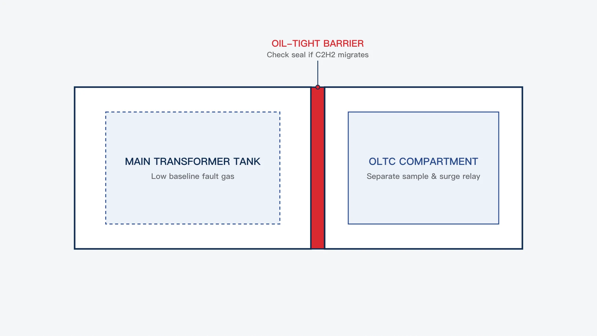
Separating the two oil volumes prevents arc byproducts—carbonized oil particles, moisture, and switching gases—from contaminating the main winding insulation. Because the diverter switch breaks load current repeatedly over its service life, OLTC oil ages faster and accumulates different chemical signatures than the main tank’s insulating oil.
Before scheduling any sampling or outage, confirm the transformer’s rated tapping arrangement and voltage steps from its rating plate; see how to read a transformer nameplate to verify the exact tap range and vector group in the asset record.
What to Test During On-Load Tap Changer Maintenance
A complete on-load tap changer maintenance program combines laboratory oil diagnostics with mechanical and protective-relay verification. Skipping either side leaves blind spots: clean oil cannot catch a sluggish motor drive, and a working drive cannot reveal degraded dielectric strength or coked contacts.
| Maintenance Domain | Specific Test or Inspection | What It Detects | Primary Record / Reference |
|---|---|---|---|
| Dielectric Oil Quality | Breakdown voltage (BDV), moisture content, acidity, and suspended carbon | Dielectric loss from arcing carbon, water ingress, and oil oxidation | OEM manual & oil test log |
| OLTC Dissolved Gas Analysis | Separate compartment sampling under IEC 60567 and gas chromatography | Abnormal arcing energy, contact overheating, and coking trends | Operation counter + IEEE C57.139 |
| Main-Tank Cross-Check | Simultaneous main-tank DGA sample compared against OLTC gases | Barrier gasket or seal leakage migrating OLTC acetylene into main tank | Main-tank DGA baseline |
| Drive & Selector Mechanism | Motor-drive current/timing, counter reading, and tap-position alignment | Mechanical binding, slipped couplings, and incomplete tap transitions | OEM mechanical checklist |
| Protective Devices | OLTC oil-surge relay, breather desiccant, and pressure-relief inspection | Sudden diverter fault surge, moisture breathing path, and stuck floats | Site protection test sheet |
Deterministic Selection Rule: Execute dielectric oil tests and DGA trending together at every planned OLTC service interval, and trigger an immediate barrier-seal investigation whenever acetylene appears unexpectedly in the main transformer tank alongside a matching OLTC signature.
Dielectric Oil Condition vs. Fault-Gas Analysis
Dielectric oil tests—breakdown voltage, water content, and acidity—evaluate whether the OLTC oil can still insulate live diverter contacts and transition resistors during switching. Heavy carbon suspension from arcing-in-oil switching degrades dielectric margin even when the tap changer mechanism operates smoothly.
Dissolved gas analysis answers a different question: whether internal switching arcs are behaving normally or shifting toward contact coking, sluggish transition, or abnormal overheating. Just as in main-tank diagnostics covered in transformer oil test results explained: DGA and Buchholz gas, a passing breakdown-voltage result never clears an abnormal fault-gas trend.
Mechanical Drive, Counter, and Protective Relay Checks
Every OLTC oil test must be logged alongside the mechanical operation counter reading at the exact time of sampling. Comparing gas concentration or oil darkening without knowing how many tap operations occurred between samples makes trend analysis impossible.
During planned outages, maintenance teams also verify the motor-drive mechanism, limit switches, local-to-remote tap-position indicator agreement, and the dedicated OLTC oil-surge relay. If a transformer with an OLTC has been sitting idle or in storage prior to commissioning, collect baseline oil samples from both compartments before energization following testing a transformer idle for years before re-energizing.
How to Read OLTC Gases: Arcing-in-Oil vs. Vacuum Tap Changers
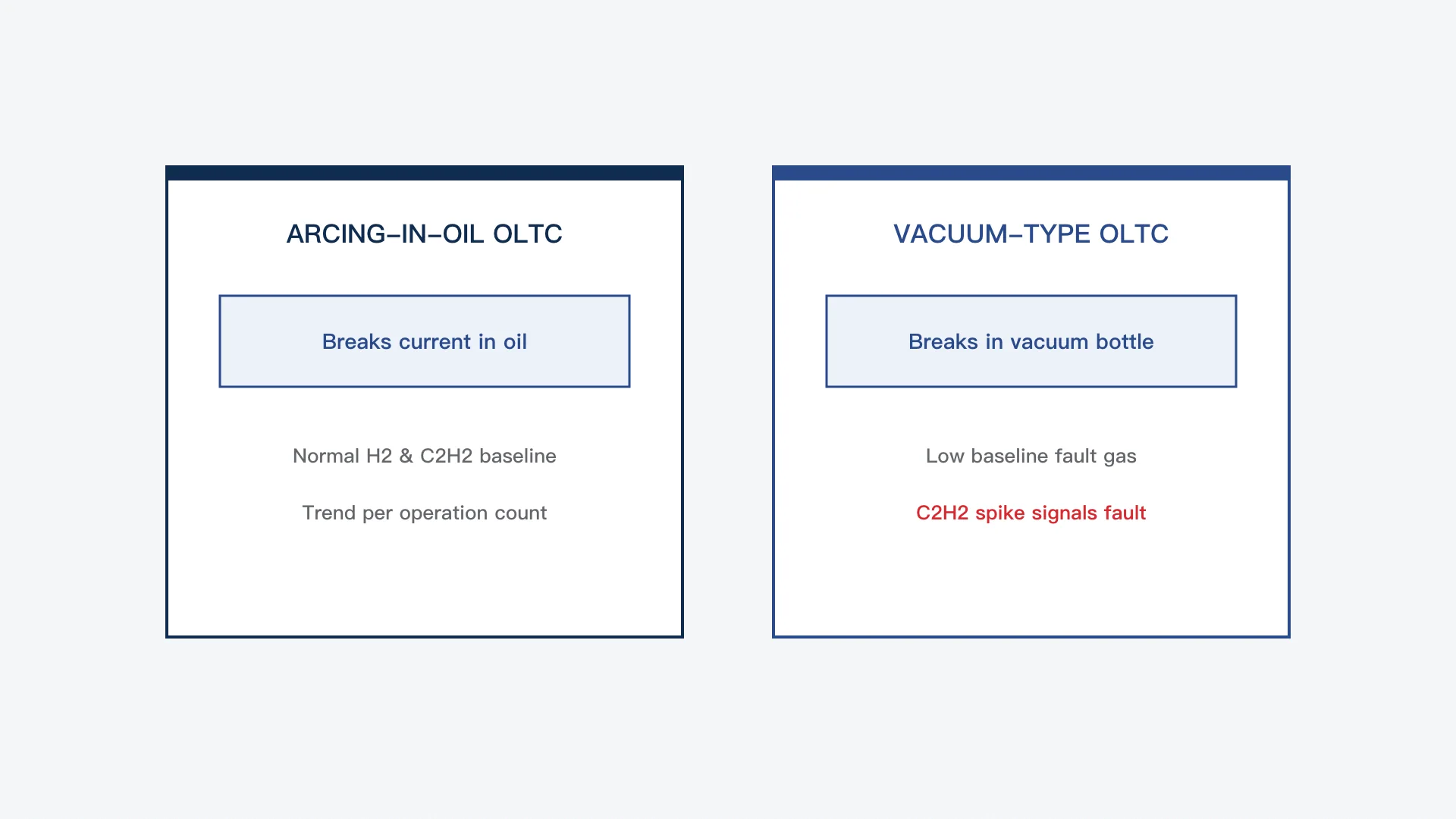
Reading OLTC dissolved gas results starts with identifying the switching technology inside the diverter compartment. Conventional arcing-in-oil tap changers and vacuum-type tap changers produce completely different normal gas baselines under IEC 60214-1 and IEEE C57.139.
Why Main-Tank IEC 60599 and IEEE C57.104 Limits Trigger False Alarms
IEC 60599 explicitly notes that standard main-tank gas ratios and transformer concentration norms do not apply directly to oil-type load tap changers where normal operation involves arcing in oil. Similarly, applying standard main-tank IEEE C57.104 condition tables to an arcing-in-oil OLTC routinely flags a healthy unit as an immediate fault.
Instead, diagnostic engineers apply dedicated OLTC guidance—such as IEEE C57.139—that evaluates gas concentrations and ratios against peer populations of the same tap-changer family, resistor or reactor design, and accumulated operation count.
| OLTC Switching Type | Normal Switching Medium | Expected Baseline DGA Profile | Primary Red-Flag Signal |
|---|---|---|---|
| Conventional Arcing-in-Oil OLTC | Mineral oil inside diverter compartment | Elevated hydrogen and acetylene from normal tap arcs | Sharp step-change in gas-per-operation rate or rising ethylene/methane thermal shift |
| Vacuum-Type OLTC | Sealed vacuum interrupter bottle | Low baseline gases comparable to a healthy main tank | Unexpected appearance or rise of acetylene or hydrogen |
Deterministic Selection Rule: Interpret conventional arcing-in-oil OLTC gases strictly by generation rate per tap operation and thermal-to-arcing ratio shifts, while treating any new acetylene or hydrogen spike in a vacuum-type OLTC as an immediate vacuum-bottle or contact-fault warning.
Reading Thermal Shifts and Coking in Arcing-in-Oil OLTCs
In a conventional arcing-in-oil diverter switch, steady hydrogen and acetylene reflect routine current interruption. What signals trouble is a sudden change in the ratio between thermal hydrocarbon gases—ethylene, methane, and ethane—and normal switching gases, or a steep jump in gas generation per operation.
Those thermal shifts commonly point to contact coking, high resistance at selector or reversing switches, sluggish spring-driven diverter transitions that prolong arc duration, or overheated transition resistors.
Vacuum-Type OLTCs: When Acetylene Means Trouble
Vacuum-type OLTCs extinguish the switching arc inside sealed vacuum interrupter bottles rather than in the surrounding insulating oil. Under normal service, their compartment oil should remain nearly free of arcing gases.
Because normal switching does not generate acetylene in the oil, finding rising acetylene or hydrogen in a vacuum-type OLTC points toward a compromised vacuum interrupter, an auxiliary contact arcing in oil, or a loose internal connection—requiring immediate investigation before returning the unit to normal tap operation.
Detecting Barrier Leaks Between the OLTC and Main Tank
Cross-contamination between the OLTC compartment and the main transformer tank is one of the most frequent causes of confusing DGA reports. When an oil-tight barrier gasket, shaft seal, or shared breather piping leaks, acetylene-rich OLTC oil migrates into the main tank.
| Main-Tank vs. OLTC Observation | Most Likely Mechanism | Required Diagnostic Action |
|---|---|---|
| Main tank shows unexpected acetylene matching OLTC profile; main-tank thermal gases flat | Oil or gas migration across barrier seal from arcing OLTC | Inspect compartment barrier, seals, and equalizing/breather piping before condemning windings |
| Main tank shows rising acetylene and ethylene while OLTC compartment stays unchanged | Active internal fault inside the main transformer tank | Follow main-tank out-of-service and internal-fault escalation procedures |
| OLTC compartment oil darkens rapidly with rising thermal gases; main tank clean | Diverter contact wear, coking, or sluggish mechanism inside OLTC | Schedule OLTC inspection, oil filtration/replacement, and contact servicing per OEM manual |
Deterministic Selection Rule: Always compare main-tank and OLTC DGA reports side by side before diagnosing an internal main-winding arc whenever an oil-immersed transformer carries an arcing-in-oil tap changer.
Planning OLTC Service Intervals and Oil Filtration
Maintenance intervals for an OLTC are governed by whichever limit arrives first in the manufacturer’s manual: elapsed calendar time or cumulative tap-changer operation count. High-duty industrial or renewable-interconnection transformers that regulate voltage dozens of times per day reach oil-carbonization and contact-wear thresholds far sooner than lightly tapped utility units.
Routine servicing typically includes draining or filtering carbonized diverter oil, flushing sediment from the compartment floor, inspecting transition resistors and arcing contacts for wear, and recording a fresh post-service oil and DGA baseline. When specifying or reviewing oil-immersed power transformers across CANGO’s Power Transformers portfolio—including sealed distribution units such as the S11-M oil-immersed distribution transformer series for 10 kV and 20 kV networks, which are distinct from larger OLTC-equipped power transformers—engineers should confirm tap-changer type, compartment isolation, sampling-valve access, and OEM servicing intervals during project specification.
Frequently Asked Questions
Can you use main-tank DGA limits to evaluate an arcing-in-oil OLTC?
No—main-tank frameworks such as standard IEC 60599 transformer tables and IEEE C57.104 condition limits are calibrated for units that do not arc in oil during normal service. Applying them directly to a conventional arcing-in-oil OLTC produces false alarms; use dedicated OLTC guidance such as IEEE C57.139 and track gas generation per operation count instead.
Why is there acetylene in my transformer main tank if the windings are healthy?
When a transformer has an arcing-in-oil OLTC, unexpected acetylene in the main tank—especially without matching thermal fault gases or a Buchholz surge event—often indicates an oil or gas leak across the barrier seal or shared breather path between the OLTC compartment and the main tank.
How often should OLTC oil be tested or replaced?
No single universal interval fits every tap changer; service and oil-sampling schedules are set by the tap-changer OEM manual based on both calendar time and cumulative operation counter readings. Always sample after abnormal oil-surge relay events or unusual jumps in tap operations.
What is the difference between DGA in a vacuum OLTC and a conventional OLTC?
A conventional OLTC breaks load current directly in mineral oil, producing a normal baseline of hydrogen and acetylene, whereas a vacuum-type OLTC interrupts current inside a sealed vacuum bottle and should maintain low baseline gases in the surrounding oil.
References
- International Electrotechnical Commission (IEC), IEC 60214-1: Tap-changers – Part 1: Performance requirements and test methods (Edition 2.0, 2014 — standard scope covering resistor/reactor, oil-immersed, and vacuum tap-changers referenced).
- IEC / IEEE, IEC/IEEE 60214-2: Tap-changers – Part 2: Application guidelines (application guidance scope referenced).
- International Electrotechnical Commission (IEC), IEC 60567: Oil-filled electrical equipment – Sampling of free gases and analysis of free and dissolved gases in mineral oils and other insulating liquids – Guidance (Edition 5.0, 2023 — sampling guidance scope referenced).
- International Electrotechnical Commission (IEC), IEC 60599: Mineral oil-filled electrical equipment in service – Guidance on the interpretation of dissolved and free gases analysis (Edition 4.0, 2022 — standard scope and OLTC limitation noted).
- IEEE Standards Association, IEEE Std C57.139: IEEE Guide for Dissolved Gas Analysis in Transformer Load Tap Changers (dedicated OLTC DGA framework scope referenced).
- CANGO Power (Zhejiang Kangge Electric Co., Ltd.), Power Transformers and S11-M Oil-Immersed Distribution Transformer (CANGO product category and sealed distribution transformer context).