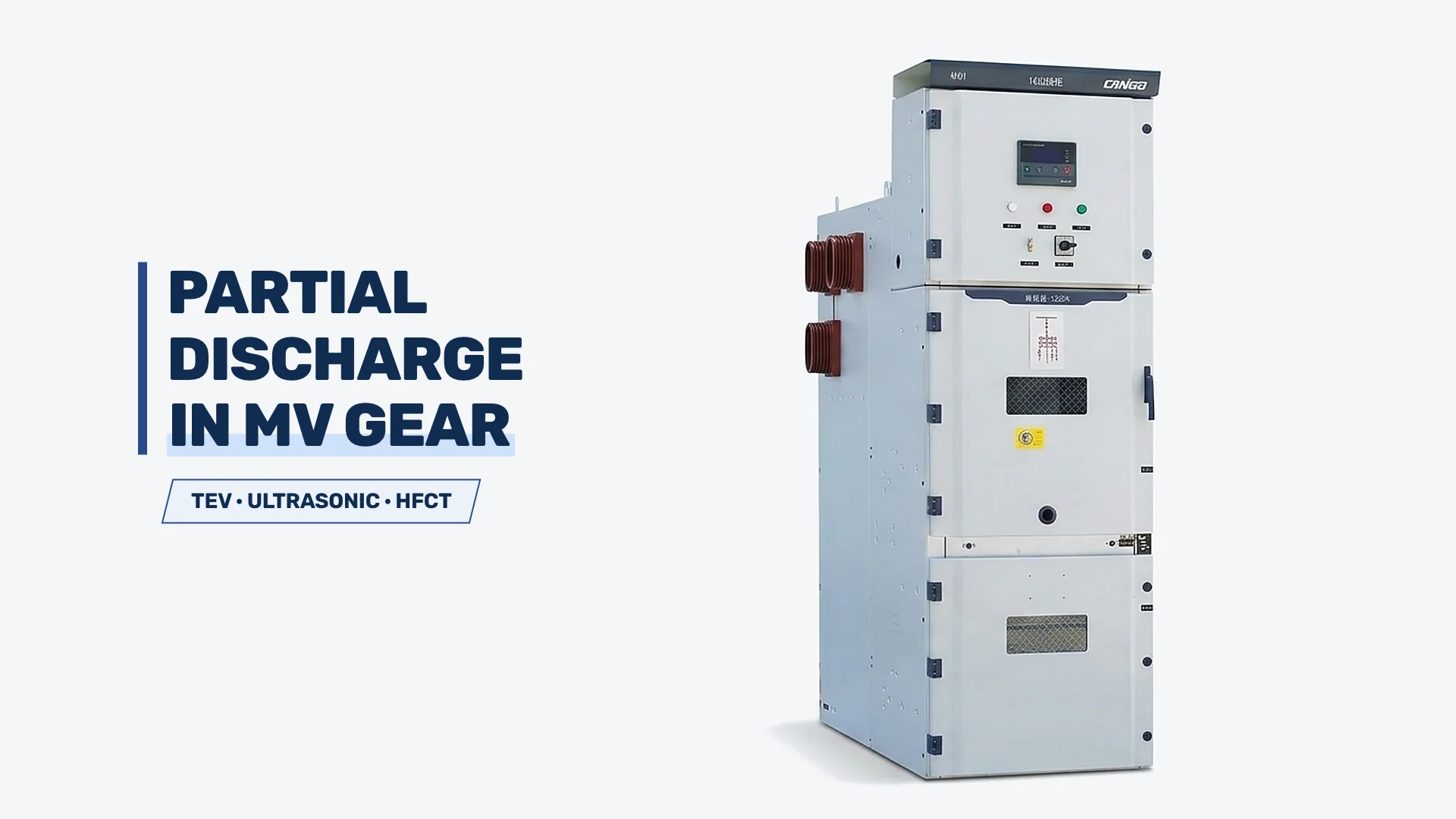
Partial discharge in medium voltage switchgear is localized by pairing three complementary online sensors—transient earth voltage (TEV), airborne ultrasonic, and high-frequency current transformers (HFCT)—so that internal solid-insulation voids, open-air surface tracking, and cable-termination defects cannot hide behind a single sensor’s blind spot. Because non-conventional online readings under IEC TS 62478 cannot be translated into a universal pass/fail dBmV cutoff, field triage relies on background-noise subtraction, adjacent-cubicle contrast, and humidity or load correlation before scheduling a de-energized outage.
| Observed Field Signal | Most Probable Discharge Mechanism | Primary Localization Zone | Immediate Triage Focus |
|---|---|---|---|
| Elevated TEV localized on one cubicle door; zero ultrasonic signal | Internal void in cast-resin insulation or floating metal hardware | Epoxy spouts, busbar support insulators, or cast-resin CTs | Confirm against adjacent panels and external substation noise before planning outage |
| Crisp ultrasonic crackling or hissing at rear/cable-door seams; audible hum or ozone odor | Surface tracking or corona across contaminated or damp insulation | Cable-termination sheds, stress cones, or damp busbar clearances | Log room humidity immediately; verify anti-condensation heaters and plan de-energized inspection |
| Strong HFCT pulse on cable earth screen with lower TEV on upper busbar chamber | Field-workmanship defect in cable termination or nearby cable joint | MV cable termination stress cone, semicon cutback, or screen earth bond | Separate cable-side fault from switchgear assembly before ordering cubicle parts |
| Uniform elevated TEV across the entire switchgear lineup | External radio-frequency interference, lighting ballasts, or upstream overhead corona | Outside the metal-clad lineup | Establish room background baseline on non-energized metalwork before condemning any bay |
Use this triage table to route the first survey pass: if every panel in the row reads identically, suspect external electromagnetic interference first; if one bay stands out sharply above its neighbors, narrow the source between the cabinet’s fixed insulation and the cable compartment before scheduling switching.
Online Detection Methods and Physical Blind Spots (TEV, Ultrasonic, HFCT)
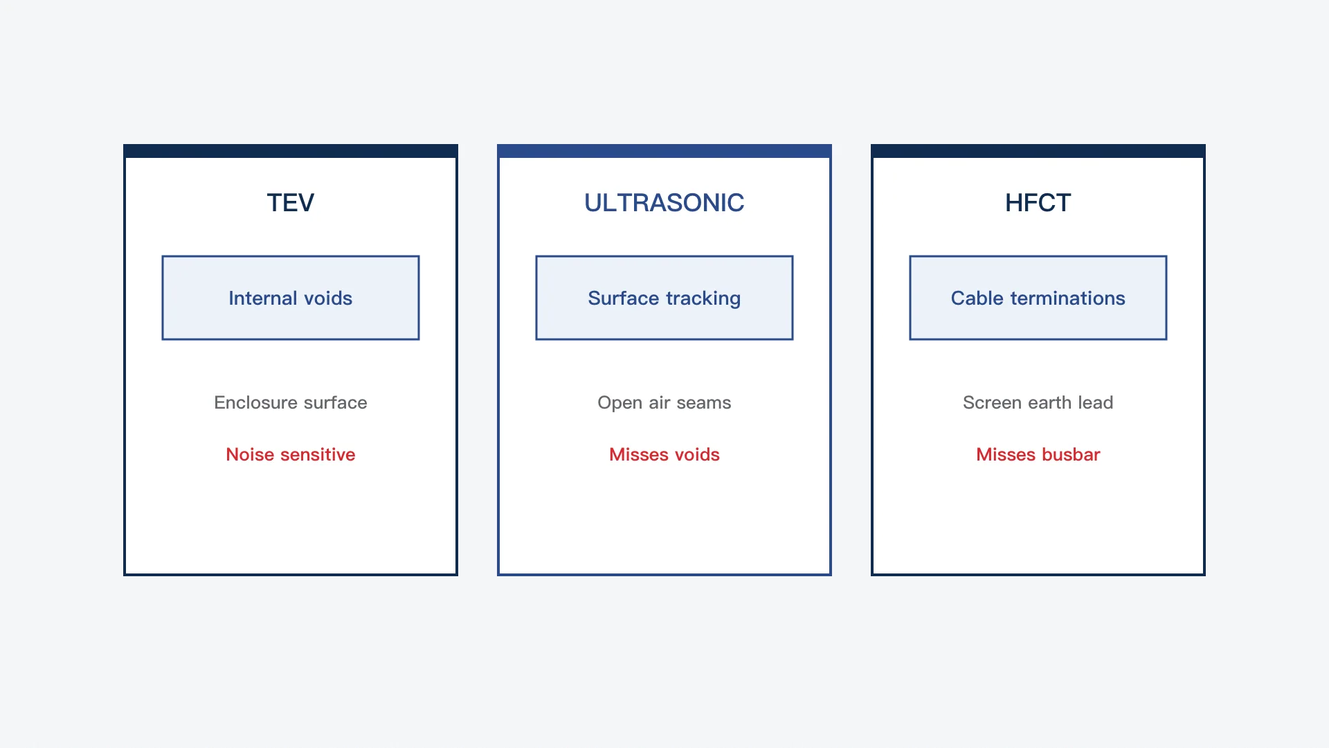
No single handheld sensor detects every form of partial discharge in medium voltage switchgear because internal voids, surface tracking, and cable-screen discharges couple energy into the enclosure through completely different physical paths. IEC TS 62478 defines electromagnetic and acoustic measurement methods as complementary tools precisely because relying on one channel alone guarantees missed defects.
| Detection Method | Physical Coupling Path | Defects Caught Reliably | Inherent Blind Spot / False-Positive Trap |
|---|---|---|---|
| Transient Earth Voltage (TEV) | High-frequency electromagnetic pulse induced on outer grounded steel enclosure via capacitive gaps | Internal voids in cast-resin CTs/spouts, floating metal shields, severe internal arcing | Vulnerable to external RF noise, switch-mode power supplies, and neighboring energized feeders |
| Airborne Ultrasonic (Acoustic) | Acoustic pressure wave escaping through door seams, vents, or viewing slots | Surface tracking, corona on sharp edges, damp or salt-contaminated cable terminations | Completely blind to sealed internal voids inside solid epoxy that produce no airborne acoustic path |
| High-Frequency Current Transformer (HFCT) | Inductive clamp around cable metallic screen earth lead | Cable-termination stress-cone defects, semicon cutback errors, nearby cable joints | Misses isolated upper-chamber busbar or breaker-compartment voids with no return path through the cable screen |
Deploy TEV and ultrasonic together on every routine walkdown of air-insulated metal-clad switchgear, and add HFCT clamping whenever rear-door TEV or ultrasonic readings point toward the cable compartment.
Why TEV Alone Triggers False Outages
Transient earth voltage probes measure radio-frequency pulses traveling along the exterior of grounded metal panels, which makes them fast for screening sealed compartments without opening doors. However, substation rooms are electrically noisy environments: fluorescent or LED drivers, variable-frequency drives, adjacent transformer bushings, and nearby radio transmitters inject steady background pulses onto grounded steelwork.
Taking a TEV reading on a single panel without first measuring background noise on an isolated metal door frame or switchgear room steelwork creates false alarms. Authentic internal partial discharge peaks sharply on one panel and attenuates noticeably on adjacent cubicles to the left and right, whereas external interference stays relatively flat across the entire lineup.
Why Ultrasonic Detection Requires an Unobstructed Air Path
Airborne ultrasonic sensors convert high-frequency acoustic emissions from surface corona and tracking into audible crackling and relative intensity readings. Because ultrasonic waves attenuate rapidly through solid steel plates, the probe must be scanned slowly along door gaskets, louvers, and panel seams where an open air path exists into the energized compartment.
A completely quiet ultrasonic scan never proves an air-insulated cubicle is free of partial discharge. An internal void trapped inside a cast-resin current transformer or epoxy breaker spout radiates zero airborne sound until the defect breaks through to the outer surface—by which point insulation breakdown may already be imminent.
Where HFCT Separates Cable Defects from Switchgear Insulation
Clamping a split-core HFCT around the earth connection of a medium-voltage cable metallic screen captures high-frequency discharge current pulses traveling directly down the cable shield. Because the cable termination sits at the exact boundary between the field-installed power cable and the factory-built switchgear bay, HFCT measurements provide the clearest signal separation between cable-side defects and busbar-chamber voids.
Separating Cabinet Insulation Defects from Cable Terminations
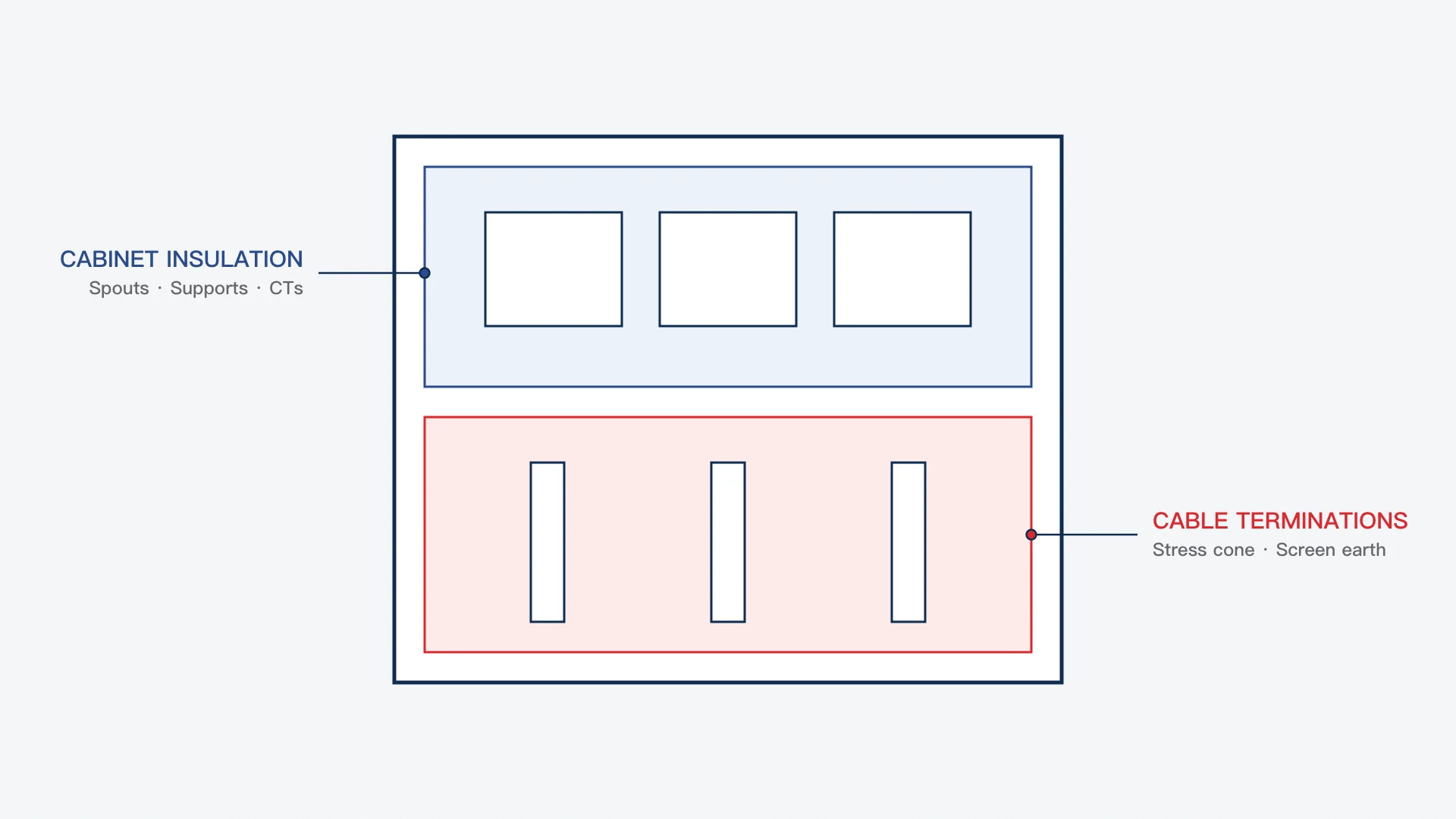
Localizing whether partial discharge originates inside the switchgear’s factory-assembled insulation or inside a field-installed cable termination is critical before taking a feeder offline and mobilizing parts. In air-insulated metal-clad switchgear rated 12–40.5 kV, the cable compartment routinely accounts for the highest share of field partial discharge because terminations are hand-assembled on site under variable humidity, dust, and space constraints.
| Inspection Zone | Typical Components in Zone | Common Field PD Drivers | Primary Ownership / Supply Boundary |
|---|---|---|---|
| Upper Cabinet & Breaker Insulation | Cast-resin epoxy spouts, busbar support insulators, cast-resin CTs/VTs, phase barriers | Internal resin voids, loose metallic shield earth connections, cracked supports, dust plus condensation | Switchgear manufacturer equipment scope (factory routine tested before shipment) |
| Lower Cable Compartment Terminations | Heat-shrink or cold-shrink termination kits, stress-control cones, cable lugs, screen earth braids | Improper semicon cutback, trapped air under stress cone, insufficient phase-to-phase/phase-to-earth clearance, moisture ingress | Cable-accessory supplier and site installation/EPC contractor scope |
Establish which zone carries the dominant signal before opening the bay: high rear-door ultrasonic crackling combined with strong HFCT screen pulses points first to the cable termination and compartment humidity, whereas localized front/top TEV peaks with weak HFCT activity point toward epoxy spouts, CTs, or busbar supports.
Field Workmanship Defects Inside Cable Terminations
Medium-voltage polymeric cables rely on a smooth electric-field transition where the outer semiconductive layer ends inside the termination kit. A knife score cut into the primary XLPE insulation during stripping, a ragged semiconductive edge, or a misplaced stress-control tube concentrates electrical stress into a tiny air pocket that initiates continuous partial discharge at normal operating voltage.
Moisture compounds workmanship flaws rapidly. In humid basements, coastal substations, or unheated switchgear rooms where anti-condensation heaters fail, moisture bridges contaminated termination sheds and converts localized micro-discharges into visible white tracking powder and pungent ozone—eventually triggering a phase-to-earth flashover.
Cabinet Insulation and Compartment Access Safety Boundaries
Inside the switchgear assembly itself, partial discharge most commonly develops at loose floating metal hardware (such as an unbonded shield or loose washer in an intense electric field), cracked busbar support insulators, or degraded epoxy spouts. For broader switchgear failure modes beyond partial discharge—such as mechanical wear or bolted-joint overheating—refer to common switchgear faults and failures.
Internal visual inspection of either the cable compartment or busbar insulation must take place strictly after full isolation, proving dead, and earthing under site permit-to-work procedures. Even in compartmentalized metal-clad gear classified under IEC 62271-200 access-continuity tiers—explained in LSC and IAC classifications for medium-voltage switchgear—no service-continuity category permits entering an energized cable compartment.
(Note: For gas-insulated switchgear where partial discharge behavior depends on pressurized insulating gas chemistry rather than open air paths, see SF6 vs g3 vs dry air in GIS partial discharge tests.)
Why Online PD Readings Cannot Use a Universal Threshold (IEC 60270 vs. IEC TS 62478)
Maintenance teams frequently look for a single universal dBmV or pC alarm line to condemn a switchgear panel on the spot, but applying a fixed number across different switchgear designs and substation environments causes both missed failures and unnecessary outages. Understanding the distinction between IEC 60270 and IEC TS 62478 explains why online triage must remain comparative and trend-based.
IEC 60270 governs conventional charge-based partial discharge testing, quantifying apparent charge in picoCoulombs (pC) inside a calibrated test circuit under controlled alternating or direct voltage. That calibrated method applies to factory routine tests, type tests, and specialized offline commissioning tests where external noise is controlled and exact capacitance calibration is possible.
IEC TS 62478 covers non-conventional electromagnetic (HF, VHF, UHF) and acoustic methods used on energized equipment in service. Because pulse attenuation depends heavily on cabinet steel thickness, door gasket geometry, cable routing, and sensor placement, an online TEV or ultrasonic reading cannot be converted mathematically into calibrated pC values.
| Measurement Context | Governing IEC Reference | Measured Quantity | Valid Engineering Use |
|---|---|---|---|
| Factory Routine / Offline Calibrated Test | IEC 60270 (Ed. 4.0) | Calibrated apparent charge (pC) | Acceptance testing of switchgear components and assemblies under controlled voltage and low background noise |
| Online Energized Field Screening | IEC TS 62478 | Relative electromagnetic (TEV/HFCT) and acoustic (ultrasonic) pulse trends | Comparing adjacent cubicles, tracking change over time, checking humidity/load sensitivity, and localizing suspect bays |
Never compare an online handheld TEV value against an IEC 60270 factory acceptance pC limit; instead, evaluate every online scan against room background noise, identical neighboring cubicles, and the panel’s own historical trend.
Pre-Outage Triage Ladder and Procurement Boundary Checks
Turning an abnormal partial discharge survey into a controlled maintenance action follows three clear branches grounded in repeatability, spatial localization, and environmental correlation. Routine walkdown cadence and broader preventive inspection logs belong in the medium-voltage switchgear maintenance checklist; the ladder below governs what to do once a suspect PD signal appears.
| Triage Branch | Verified Survey Evidence | Required Action |
|---|---|---|
| Branch A: Baseline & Monitor | Signal uniform across entire row (external noise confirmed) or low, flat reading matching room background with zero ultrasonic crackling | Record background baseline, room humidity, and load; keep unit on normal inspection cycle |
| Branch B: Shorten Interval & Check Environment | Localized elevation on one bay with intermittent ultrasonic activity tied to high humidity or failed space heaters; no ozone odor or rapid upward trend | Verify and restore cabinet anti-condensation heaters/ventilation, re-scan under dry and humid conditions, and trend pulse stability on a shortened cycle |
| Branch C: Schedule De-Energized Inspection | Sustained localized TEV/HFCT peak clearly above adjacent cubicles, persistent ultrasonic crackling at seams, ozone odor, or rapidly rising trend | Plan controlled outage under site permit; isolate, prove dead, earth, and inspect cable terminations, epoxy spouts, supports, and CTs before re-energizing |
Escalate immediately to Branch C whenever audible hissing, ozone odor, or a steeply rising localized signal is detected—waiting for the next annual outage invites an unscheduled cable-compartment flashover.
Specifying Medium-Voltage Switchgear to Minimize Field PD Risk
When specifying new 12–40.5 kV installations across CANGO’s Medium-Voltage Switchgear portfolio—including withdrawable metal-clad assemblies such as KYN28-12 12kV Metal-Clad Switchgear and KYN61-40.5 40.5kV Medium Voltage Switchgear—project engineers reduce long-term partial discharge exposure by addressing both factory equipment and site-interface boundaries during quotation:
- Confirm cable-compartment dimensions and clearances: Verify cable entry height, bending radius, and termination clearance so site jointers are not forced to bend stress cones tightly against metal partitions.
- Specify anti-condensation protection: Include thermostatically or hygrostatically controlled space heaters in humid, coastal, or intermittently loaded substations to prevent surface moisture tracking.
- Separate equipment supply from cable-accessory installation: CANGO supplies medium-voltage switchgear assemblies and routine factory testing documentation, while cable termination kits, site cable jointing, and online field PD testing services remain within the EPC, utility, or specialized testing contractor’s scope.
Frequently Asked Questions
Can ultrasonic testing alone rule out partial discharge in medium voltage switchgear?
No—airborne ultrasonic probes detect surface tracking and corona only when an open air path lets sound waves escape through door seams or vents. Internal voids inside cast-resin current transformers, epoxy spouts, or cable stress cones produce no airborne acoustic signature until they break through the surface, which is why ultrasonic scans must be paired with TEV and HFCT checks.
Why do cable terminations cause so many partial discharge alerts inside metal-clad switchgear?
Cable terminations are assembled manually on site inside tight lower compartments where dust, humidity, and small errors in semiconductive-layer stripping or stress-cone positioning create concentrated electric fields. Those workmanship and moisture defects initiate surface tracking or interfacial discharge long before factory-molded switchgear insulation ages.
Can online TEV readings be converted into IEC 60270 picoCoulombs (pC)?
No—IEC 60270 apparent charge calibration requires a controlled offline circuit with known capacitance injection, whereas online TEV sensors under IEC TS 62478 measure relative high-frequency enclosure pulses influenced by steel geometry and external noise. Judge online TEV results by comparing against room background noise, adjacent cubicles, and historical trends.
References
- International Electrotechnical Commission (IEC), IEC 60270: High-voltage test techniques – Charge-based measurement of partial discharges (Edition 4.0, 2025 — conventional apparent-charge PD measurement scope referenced).
- International Electrotechnical Commission (IEC), IEC TS 62478: High voltage test techniques – Measurement of partial discharges by electromagnetic and acoustic methods (non-conventional electromagnetic and acoustic PD detection and location scope referenced).
- CANGO Power (Zhejiang Kangge Electric Co., Ltd.), Medium-Voltage Switchgear, KYN28-12 12kV Metal-Clad Switchgear, and KYN61-40.5 40.5kV Medium Voltage Switchgear (CANGO product category and metal-clad switchgear scope).
- CANGO Power, SF6 vs g3 vs Dry Air in GIS: What Partial Discharge Tests Reveal, LSC and IAC Classifications for Medium-Voltage Switchgear, Common Switchgear Faults and Failures, and Medium Voltage Switchgear Maintenance Checklist (verified internal canonical owner references).