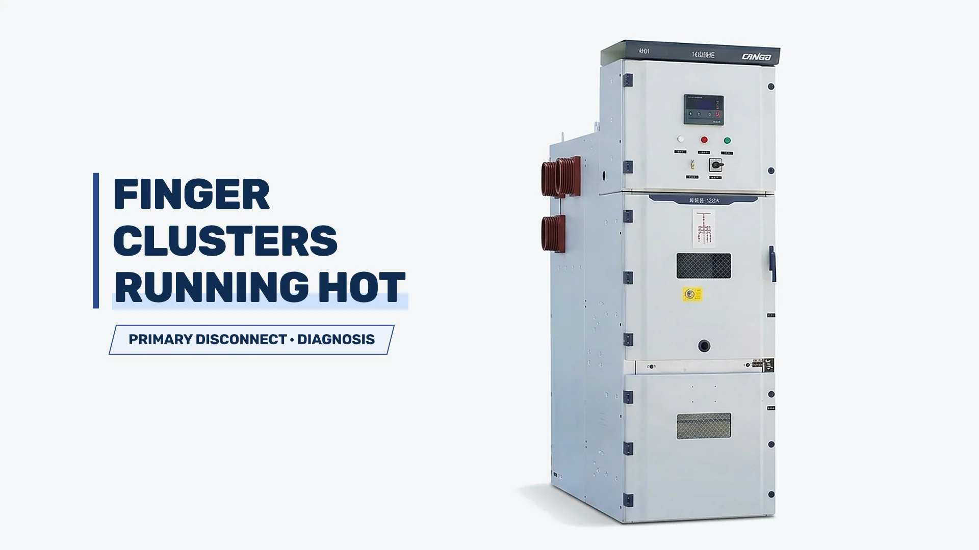
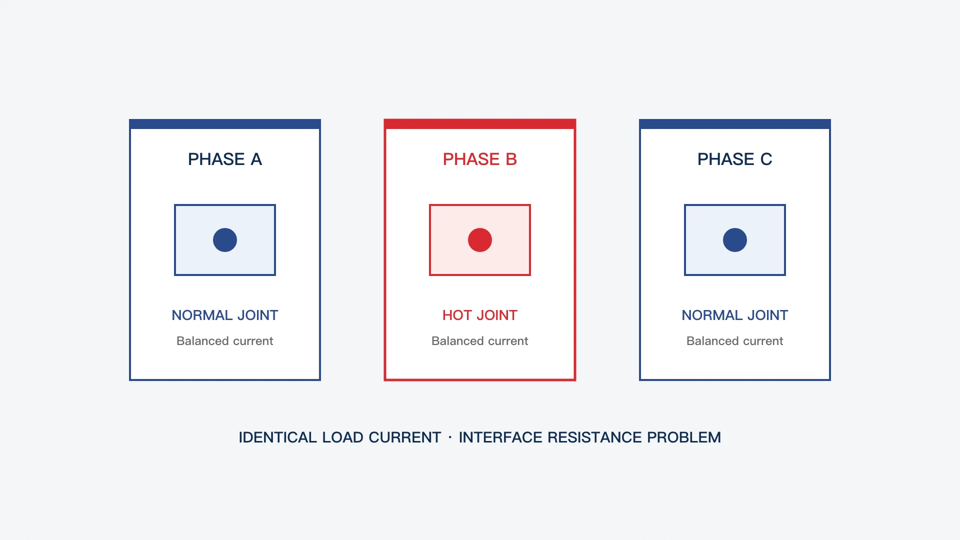
An infrared survey through a viewing window or a discoloured breaker arm showing one phase hot while the other two stay cool points directly to vacuum circuit breaker contact overheating. Before touching the breaker, compare the three phase currents on the feeder meter. Balanced currents paired with one hot joint confirm an interface resistance problem rather than a load problem; unbalanced currents indicate a different feeder or downstream investigation altogether. On a draw-out vacuum breaker in medium-voltage metal-clad switchgear, the first suspect is the primary disconnect—the finger cluster and its mating stab.
This diagnostic planning guide is written for qualified electrical engineers and maintenance leads operating medium-voltage switchgear. All internal inspection and contact-resistance measurements take place only after full isolation, proving dead, and applying earths under the site permit-to-work process; no energised-work method is presented here.
The Separable Interface Behind Vacuum Circuit Breaker Contact Overheating
The primary disconnect of a draw-out vacuum breaker pole is a separable contact system built to make and break the main circuit path every time the truck is racked in or out. Unlike a fixed-mounted breaker whose bolted busbar connections stay undisturbed for years, every draw-out pole introduces an extra sliding mechanical joint between the cubicle and the truck.
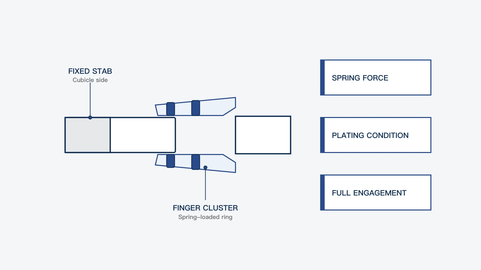
In most withdrawable designs, a fixed copper stab—also called a spade—protrudes inside the cubicle spout while a ring of spring-loaded copper fingers, known as a finger cluster or tulip contact, rides on the breaker arm (on some designs the arrangement is reversed, so the inspection applies to whichever side carries the cluster). Those fingers are normally silver-plated and held inward by garter springs or leaf springs so that phase current is shared across many parallel fingers and micro-contact spots.
Three physical conditions decide whether that separable joint stays cool under load: the normal contact force maintained by the springs around the stab, the condition of the silver plating in the working band where the stab actually seats, and full, square engagement. Because resistive heating at the interface follows the square of load current multiplied by contact resistance, even a modest rise in joint resistance turns into a steep thermal penalty once the feeder approaches rated load.
Why One Phase Overheats and Will Not Self-Heal
Each pole of a three-phase draw-out vacuum breaker is an electrically and mechanically independent contact assembly. One phase’s finger cluster can suffer spring fatigue, plating wear, or slight misalignment while the other two phases carry the exact same load current with normal contact resistance and normal operating temperatures.
That independence explains why balanced phase currents never clear a single hot pole. In high-current industrial service, plants running heavy draw-out vacuum breakers routinely discover one phase arm running hot during normal, steady load trends—and sometimes see the symptom return on another phase after an incomplete repair—because the fault lives inside the individual pole’s separable joint rather than on the power system.
Once a finger cluster runs hot, it enters a self-feeding thermal loop that will not heal on its own. Elevated temperature softens and anneals the spring material, relaxing the clamping force against the stab. Lower normal force reduces the number of microscopic metallic contact bridges carrying current, which raises contact resistance further, generates more heat at the same load, and accelerates spring relaxation. Under cyclic plant loading, a weakened cluster can appear tolerable during light shifts and then climb rapidly in temperature whenever production demand returns to rated feeder current.
For that reason, field technicians treat any finger cluster that has run hot once as mechanically suspect even after the surface looks clean. Heat may already have taken the temper out of the springs, meaning a wiped and re-racked cluster can pass an initial visual glance yet drift back into overheating under sustained service load. Worse, each subsequent thermal cycle widens the resistance gap between the damaged pole and its two healthy sister phases until insulating supports or adjacent seals begin to suffer secondary thermal stress.
The Tarnish Trap: Black-Gold Silver vs. Heat Damage
Silver plating on primary-disconnect fingers and stabs develops a dark, black-gold tarnish film over normal service life in industrial air. Trace sulfur-bearing compounds and warm enclosure air react slowly with the silver surface, producing a thin sulfide layer that looks dramatic under a flashlight. Visually, that natural silver-sulfide tarnish can look remarkably similar to copper and plating that have been discoloured by severe thermal annealing.
Relying on visual colour alone creates the tarnish trap—and leads maintenance teams into two opposite, costly mistakes. The first error is condemning healthy, tight silver-plated fingers simply because the contact band has darkened to black-gold, triggering unnecessary parts replacement and extended outages on a sound pole. When spring pressure remains strong, the mechanical wiping action of racking and micro-asperity contact through the thin tarnish film still preserves low-resistance metallic paths.
The second, more dangerous error is dismissing genuine thermal damage as harmless tarnish. When a technician wipes away surface soot or assumes dark discolouration is normal oxidation on a cluster whose springs have already lost temper, the breaker returns to service with high contact resistance and resumes heating the moment load builds. Because copper-oxide scale and heat-darkened plating share the same dark palette as benign sulfide tarnish, no naked-eye inspection can tell them apart reliably.
Colour is never proof of overheating, and blackened silver is never automatic proof of damage. Only two objective witnesses separate benign tarnish from active joint degradation: comparative temperature across the three phases under comparable load, and measured per-pole contact resistance with a documented test path.
The Cause Ladder for Primary-Disconnect Overheating
When one phase of a draw-out vacuum breaker runs hot, the underlying mechanical cause sits along a clear ladder from the finger cluster itself back to the fixed cubicle busbar. Working through these mechanisms in order prevents replacing healthy components while missing the real defect.
Spring Force Loss
Garter springs and retaining springs around the finger cluster lose tension through mechanical fatigue over years of service or through thermal annealing after an earlier hot run. As clamping force drops, individual fingers lose firm metallic contact against the stab, concentrating phase current into fewer remaining contact points and accelerating local heating. Even when individual fingers look straight, a relaxed spring allows contact resistance to climb whenever vibration or thermal expansion shifts the joint.
Worn Plating and Fretting Debris
Repeated racking cycles eventually wear silver plating thin or expose bare copper inside the working contact band where the fingers seat on the stab. Once bare copper is exposed to warm switchgear air, it oxidizes much faster than silver and raises interface resistance. At the same time, tiny micro-motions caused by vibration and daily thermal expansion-contraction cycles produce fretting debris—dark, oxidized wear particles trapped inside the contact groove that act as a resistive barrier between metal surfaces.
Bent, Cracked, or Missing Fingers
A single bent, mechanically cracked, or missing finger disrupts the uniform radial ring around the stab. Because the remaining fingers must carry the entire phase current without the missing parallel paths, their current density rises immediately, pushing those surviving fingers toward localized overheating and spring relaxation. Often the damage begins during rough handling on a maintenance bench or an unguided truck insertion that catches the leading edge of one finger.
Angled or Incomplete Engagement
If the breaker truck approaches the cubicle stab slightly off-center or stops short of full insertion, the stab enters the cluster at an angle or rests near the outer edge of the fingers. Only a small fraction of the contact ring engages the stab, overloading those few fingers under normal feeder current. Witness marks on the stab—showing heavy contact on one side and untouched plating on the opposite face—confirm uneven engagement without guessing. (Broader racking-mechanism interlocks and closing-coil failures belong to separate mechanical investigations and are not opened here.)
Fixed-Side Stab and Bolted Joint
The hot spot detected on an infrared scan is not always on the withdrawable breaker truck. The fixed stab inside the spout and the bolted connection behind it—where the stab transitions to the main busbar or cable termination—sit in the exact same current path. Heat generated at a loose rear bolted joint conducts straight along the copper stab into the primary-disconnect region, mimicking a finger-cluster fault on thermography. Failing to localize which side of the joint is generating heat leads to ordering replacement clusters when the real fault is on the fixed cubicle side.
Wrong or Mixed Parts from a Previous Repair
A recurring hot joint on the same or adjacent phase frequently traces back to a past emergency repair. Mixing fingers from different spring batches, installing non-matching cluster hardware, or reusing old retaining springs alongside new fingers creates uneven contact pressure around the ring and guarantees uneven current sharing. Because individual fingers look nearly identical at a glance, mismatched components often go unnoticed until the next thermal survey under heavy plant load.
Diagnosis in Order: From Thermography to Decision Branches
Diagnosing an overheating pole requires disciplined sequence rather than jumping straight to disassembly. General joint-overheating fundamentals—such as ambient cooling checks and standard bolted-connection inspection across switchgear compartments—are covered in the common switchgear faults and failures guide; the sequence below focuses specifically on isolating the draw-out primary disconnect.
Start with operating records and thermal comparison while the feeder is energized under comparable, representative load. Compare the suspect phase against its two sister phases at the exact same viewing angle, emissivity setting, and joint location, remembering that there is no universal temperature difference or fixed temperature band that condemns a joint on its own—only phase-to-phase divergence at matched load that justifies a planned outage. Scanning all three phases during the same load window eliminates ambient-temperature drift and solar or room-ventilation effects from the comparison.
Next, isolate the feeder, rack the breaker truck out, prove dead, and apply site earths under permit before inspecting both sides of the interface. Examine every finger in the cluster for uneven wear tracks, localized burning, worn-through plating in the working band, displaced or relaxed springs, and physical distortion, and inspect the fixed cubicle stab for scoring, alignment marks, and rear-joint tightness—aligning the inspection items with the medium-voltage switchgear maintenance checklist.
Before disturbing the contacts further, measure static per-pole contact (loop) resistance across each de-energized phase using a micro-ohmmeter. Document the exact current-injection and voltage-pick-off points—whether measuring across the breaker pole alone (upper arm to lower arm, including the vacuum interrupter and both finger clusters) or across the coupled breaker-and-stab assembly—because a resistance reading without a documented path cannot isolate a suspect joint. If the racked-out breaker pole measures balanced across all three phases while the in-service joint ran hot, that contrast immediately directs attention toward the fixed stab, its rear bolted termination, or engagement alignment inside the cubicle. Evaluate each pole by comparing all three phases against one another, against the commissioning or previous maintenance baseline, and against the breaker manufacturer’s stated limits.
| Diagnostic Observation | Engineering Interpretation | Mandatory Decision Branch |
|---|---|---|
| Three-pole resistance balanced and within baseline/manufacturer values; springs tight; plating intact with black-gold film only | Benign silver tarnish without active joint degradation | Branch A: Return breaker to service, log the inspection and resistance baseline, and schedule a shortened thermal follow-up |
| One pole elevated relative to sister phases or baseline, or visible finger wear, burning, plating loss, or suspect spring tension | Active primary-disconnect degradation at the finger cluster | Branch B: Replace the affected finger cluster as a complete manufacturer-matched set, re-measure loop resistance, and record the new baseline |
| Damage localized on the fixed cubicle stab/rear bolted joint, or repeated overheating after a full cluster replacement | Fault lies upstream of the breaker truck or involves cubicle alignment | Branch C: Keep the circuit out of service and escalate to the switchgear manufacturer before re-energizing |
Repair Rules for Finger Clusters and Springs
Once a finger cluster fails inspection or contact-resistance comparison, half-measures turn a single outage into a recurring fault. Follow strict replacement discipline so the repaired pole matches the electrical and mechanical symmetry of the healthy phases:
- Replace as a matched set: Never replace individual fingers or mix old and new fingers or springs inside a single cluster; install the breaker manufacturer’s complete matched finger-cluster and spring assembly.
- Never polish, file, or sand plated surfaces: Abrasive cleaning strips away remaining silver plating and destroys the engineered contact geometry. Clean healthy contacts strictly using the breaker manufacturer’s approved non-abrasive procedure; if plating is worn through in the working band, replace the cluster.
- Never re-bend or re-tension springs: Heat-softened or distorted springs cannot recover original temper or uniform radial clamping force by manual bending; replace the spring assembly outright.
- Use manufacturer-specified lubricant only: Never apply generic grease or multipurpose petroleum compounds to primary disconnects, as improper grease traps debris and carbonizes under heat. Apply contact lubricant only where and exactly as specified by the breaker manufacturer.
- Verify and baseline after repair: Rack and re-measure per-pole contact resistance across the documented path after every cluster replacement, confirming phase-to-phase balance and recording the result as the unit’s new commissioning-grade baseline.
Keeping Contact Overheating from Coming Back
Preventing repeat vacuum circuit breaker contact overheating depends on trending relative changes over time rather than reacting to sudden discolouration or alarms. Schedule periodic infrared thermography rounds while feeders are carrying representative load, comparing the same phase-to-phase viewing points across consecutive surveys.
Combine energized thermal comparison with de-energized micro-ohm resistance trending during planned outages, logging every reading against the unit’s commissioning baseline and the exact test path used. Perform primary-disconnect cleaning, inspection, and servicing strictly at the intervals defined in the breaker manual and tracked through the medium-voltage switchgear maintenance checklist.
From an equipment-design standpoint, withdrawable metal-clad switchgear makes this entire primary-disconnect system inspectable and replaceable without dismantling fixed busbar chambers—as seen in CANGO’s KYN28-12 withdrawable metal-clad switchgear and KYN61-40.5 withdrawable metal-clad switchgear built for 12–40.5 kV vacuum breaker applications. When evaluating or specifying any withdrawable switchgear assembly, two practical buyer questions protect long-term maintainability: confirm whether primary-disconnect finger clusters and springs are supplied as replaceable matched sets, and verify the breaker manual’s stated contact-servicing interval before commissioning.
References
- CANGO Power (Zhejiang Kangge Electric Co., Ltd.), KYN28-12 12kV Metal-Clad Switchgear (CANGO product information confirming withdrawable metal-clad construction and vacuum circuit breaker configuration).
- CANGO Power (Zhejiang Kangge Electric Co., Ltd.), KYN61-40.5 40.5kV Medium Voltage Switchgear (CANGO product information confirming 40.5 kV withdrawable metal-clad construction).
- CANGO Power, Common Switchgear Faults and Failures (general switchgear overheating diagnostic baseline).
- CANGO Power, Medium Voltage Switchgear Maintenance Checklist (inspection intervals and contact-resistance recording discipline).