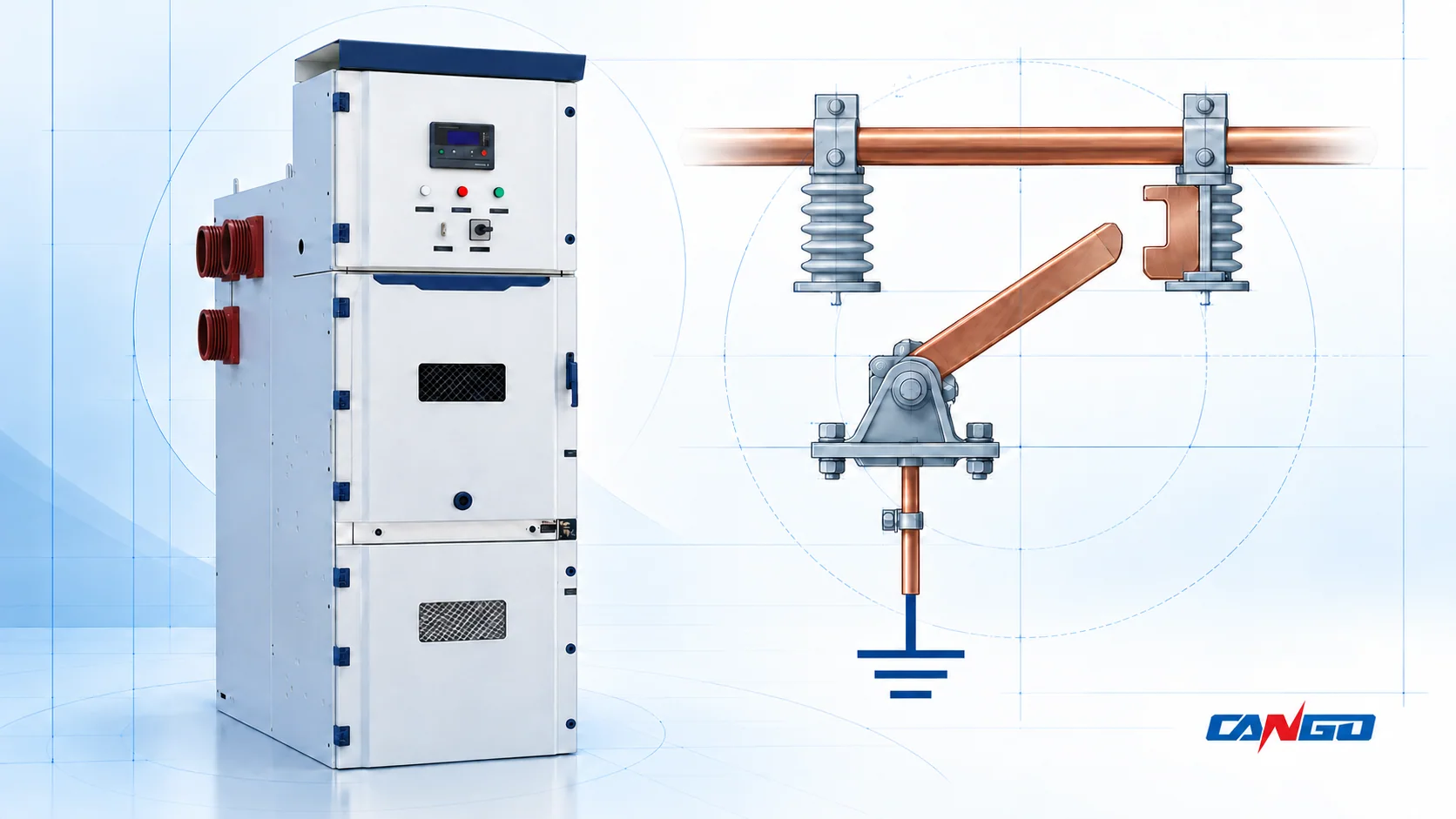
An earthing switch connects a defined section of the medium-voltage primary circuit to earth. Its associated interlocks restrain incompatible movements, closing commands or access states. A breaker-open indication, a disconnected truck or a released interlock does not by itself prove that every possible source is isolated or that a work area is safe.
The useful engineering question is therefore twofold: which conductors does the switch earth, and which conditions does each interlock actually check? Answering both requires the primary diagram, the interlock matrix and the equipment instructions. The MV switchgear selection guide provides the wider equipment context; this article explains the earthing and interlocking relationship.
Actual switching and access remain subject to authorised personnel and the approved site safety system. HSE guidance explicitly retains identification and proving-dead requirements even where automatic interlocking provides isolation. Its guidance applies to workplaces in Great Britain; it is not a global product approval. HSE HSG85, paragraphs 47–65
What an Earthing Switch Does—and What It Does Not Replace
Interruption, isolation and earthing are distinct functions. Equipment can combine them, but one function should never be inferred from another device label.
| Function | Engineering purpose | What the observed state does not establish |
|---|---|---|
| Circuit breaking | Interrupt current within the declared switching duty | An open breaker is not evidence of separation from every source |
| Isolation | Establish the specified separation from relevant sources | It does not by itself establish absence of charge or an authorised work condition |
| Circuit earthing | Connect the identified primary-circuit section to the earthing system | It does not automatically earth another section across an isolating boundary |
| Enclosure bonding | Connect exposed conductive enclosure parts to the protective earthing system | A bonded cabinet does not mean its primary conductors are earthed |
The distinction between isolation and a dead condition is set out in HSG85. HSE also distinguishes integral earthing built into switchgear from extensible and portable earthing equipment; their arrangements and inspection needs differ. A cabinet with an integral earthing switch does not therefore settle every worksite earthing requirement. HSE HSG85, definitions and earthing guidance; HSE HSG230, paragraphs 132–135
At apparatus level, IEC 62271-102 covers alternating-current disconnectors and earthing switches above 1,000 V, through 60 Hz. IEC 62271-200 addresses the prefabricated metal-enclosed assembly above 1 kV and up to 52 kV. Those are separate evidence scopes: a declared apparatus duty does not establish that a complete panel has the required earthing arrangement or interlocking behaviour. IEC 62271-102 publication information; IEC 62271-200 publication information
Read the Earthed Section from the Primary Diagram
Start with the electrical node to which the earth branch is connected. A cable-side earthing switch normally concerns the connected cable-side conductors. A busbar earthing arrangement concerns a different section, with different supply paths and isolation dependencies. The words “panel earthed” are too imprecise for a design review.
For each proposed earthing point, mark the connected conductor section and its boundaries on the single-line diagram. Identify branches, isolating interfaces and possible sources beyond the panel. Also identify the intended work area: it may lie beyond another boundary or some distance from the earthing point. HSG85 notes that suitable local earthing may be needed remotely from the main isolation point. HSE HSG85, paragraphs 63–65
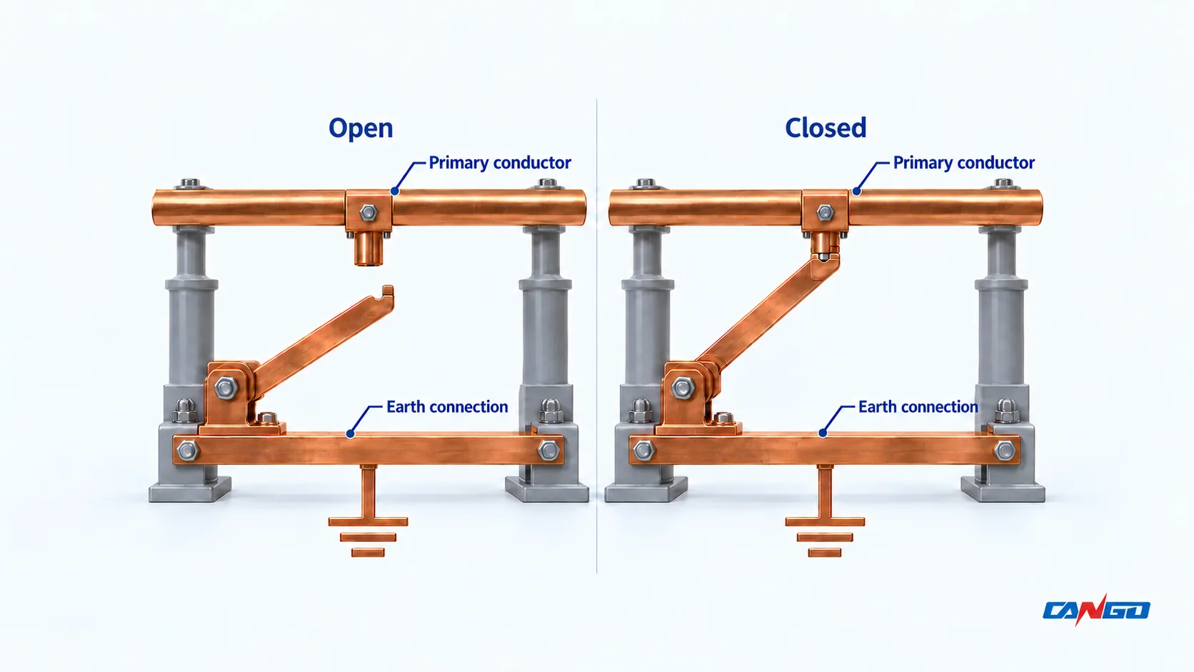
Opening the earthing switch removes that intentional connection; it does not prove the conductor is live. Closing it establishes the designed earthing path; its position alone does not verify every contact, connection or worksite condition.
For drawing orientation, use the MV single-line diagram guide. A single-line diagram locates the primary function. Detailed mechanical restrictions, control permissives and external dependencies belong in the associated interlock and control documents.
What the Interlocks Actually Prevent
An interlock ties a particular action to defined conditions. A useful interlock matrix names the action, the required states, the enforcing mechanism and the evidence available to demonstrate the result.
Keep four states separate: breaker contacts, truck primary-connection position, earthing-switch position and external-source status. “Breaker open” and “truck disconnected” are different observations. A breaker may also be capable of closing for secondary testing while its primary contacts remain disconnected, subject to the equipment design. Test and disconnected positions are not necessarily interchangeable names.
The table below is a design-review example for a withdrawable feeder with a separate cable-side earthing switch. It identifies relationships to confirm; it is not a universal IEC matrix or an operating sequence.
| Condition or proposed action | Relationship to confirm in this example | Evidence to request |
|---|---|---|
| Truck connected in service; earth closure requested | The earth-closing action is restrained while the local primary connection remains in service | Defined truck position and the mechanism or permissive enforcing the restraint |
| Cable earthing switch closed; return to service requested | Service reconnection is restrained while the cable-side earth connection remains closed | Earth-position linkage and the approved service-entry interlock |
| Truck between defined positions; breaker closing requested | Closing is restrained outside the positions authorised by the design | Position definitions, closing logic and mechanical interfaces |
| Access to a primary compartment requested | The access conditions match that compartment and the section actually earthed | Approved access arrangement, barriers, locks and equipment instructions |
| An external source can energise the cable | Local device positions alone do not resolve the external source dependency | System interlock requirements and the site isolation boundary |
Do not convert this example into “a circuit breaker must always be open whenever an earthing selector is in EARTH.” Some topologies intentionally use the breaker to complete an earthing path. For example, Hong Kong Water Supplies Department specification E-15-02 describes such an arrangement in section 3.2.4.2. Its topology-specific interlocks demonstrate why an approved scheme matters; they are not a specification for CANGO withdrawable panels. WSD E-15-02, June 2021
Mechanical, Electrical and Key Interlocks Check Different Things
Mechanical interlocks restrain movement through physical relationships. Review which movement is blocked, how position is transferred to the restraint, and whether a replacement truck or mechanism remains compatible. HSE switchgear guidance identifies interlocking and earthing arrangements as retrofit compatibility issues. HSE HSG230, paragraphs 148–154
Electrical or electromechanical interlocks use position contacts, wiring and control logic to permit or restrain an action. Ask how the offered scheme responds to loss of control power, missing or contradictory signals, and local versus remote commands. Record the declared response rather than assuming every solenoid or control system fails into the same state.
Key interlocks coordinate actions through a defined key-release and exchange arrangement. Review the complete scheme, including external panels and key custody. A key released by one device provides evidence only about the conditions represented by that scheme. The WSD specification gives a project-specific example of external key coordination and approved electromechanical interlocking; its requirements should not be generalised to all installations. WSD E-15-02, sections 3.2.4.4–3.2.4.5
Why Local Status Cannot Prove Remote Isolation
A local isolating gap separates the circuit from the local source. It does not disconnect a source at the far end of the cable. Depending on the actual network, relevant sources can include a ring connection, an interconnector, generation or another backfeed path. Assess the sources present in the project rather than adding a generic list to every feeder.
Induced voltage is another mechanism and should not be confused with direct backfeed. OSHA identifies both induced voltage and unexpected generator backfeed among the hazards addressed by protective grounding. That US workplace guidance supports the distinction; it does not prove that one integral earthing switch establishes an equipotential work zone. OSHA, Grounding for Employee Protection
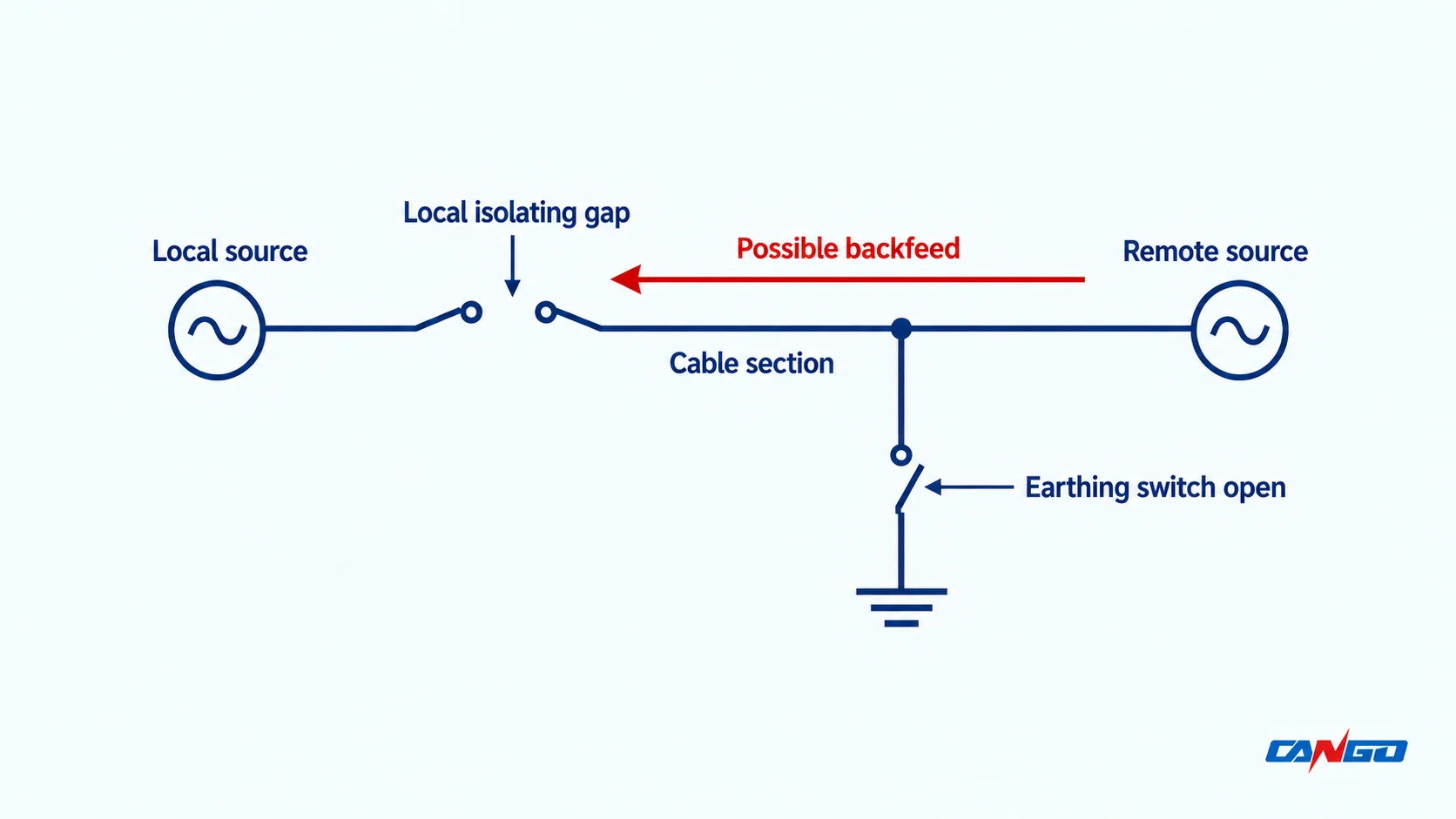
The review must therefore distinguish a device movement being permitted from the work area being verified safe. An extinguished lamp, mimic symbol or remote status tag is not that verification. HSG85 expressly retains the proving-dead requirement even when automatic interlocks achieved isolation. HSE HSG85, proving-dead guidance
Where a proposal relies on external position or voltage information, identify its source, validity conditions and failure response. A permissive cannot establish a condition that its inputs do not represent.
Making and Withstand Duties Need Separate Declarations
Earthing-switch ratings answer different questions from its interlock matrix. A mechanically correct scheme still needs an apparatus and earthing circuit suitable for the assigned electrical duty.
| Review item | Meaning for the offered scheme |
|---|---|
| Voltage and insulation basis | Match the specified system and installation conditions |
| Short-time withstand current and duration | Declare the RMS current and associated time together |
| Peak withstand duty | Verify the relevant peak duty separately from the RMS value |
| Assigned short-circuit making capability | Confirm the declared closing-on-fault duty and supporting evidence |
| Other assigned switching duties | Require an explicit declaration where the application needs them; do not infer breaking duty from making capability |
| Earthing-circuit and assembly evidence | Identify which arrangement and configuration the supporting documents cover |
The public IEC 62271-102 revision information separately identifies short-circuit making classification, while IEC 62271-200 highlights earthing-circuit ratings and tests. This is a reason to ask for explicit declarations, not to infer a rating from the cabinet name. A making capability is not permission to close onto a circuit believed to be live, and it does not turn an earthing switch into a general-purpose fault-current interrupter. IEC 62271-102; IEC 62271-200
Agree the applicable standard editions and national adoption in the project documents. No universal current, endurance class or switching capability follows from a product-family designation.
Review the Offered Scheme, Not Just the Model Name
The final review package should connect the primary arrangement to the control and mechanical evidence:
- A marked single-line diagram identifying each earthed section, isolation boundary and relevant source.
- An interlock matrix naming actions, required states, restraints and external dependencies.
- Auxiliary schematics and position definitions, including loss-of-power and invalid-signal responses.
- Compartment-access conditions, indications, key schedules and equipment instructions.
- The assigned earthing-switch duties and applicable apparatus/assembly evidence.
- An agreed verification schedule recording the actual panel scheme and revision, expected restrained or permitted outcomes, and results.
These documents serve different purposes. A witnessed functional check does not replace applicable apparatus or assembly qualification. The WSD specification illustrates this distinction by requiring assembled-switchboard interlock and control testing in addition to its equipment requirements. WSD E-15-02, section 4.1.2
For a CANGO enquiry, KYN28-12, KYN28-24 and KYN61-40.5 are cabinet-family routes against which to request the project arrangement. Their ordering information asks for control, protection and locking requirements. Their public pages do not establish one universal earthing-switch option or a complete interlock matrix.
Submit the marked diagram and required interlock relationships with the project ratings. Use the MV switchgear quotation checklist to assemble the other project inputs, and confirm the offered scheme and supporting documents before acceptance.
References
- Health and Safety Executive. Electricity at work: Safe working practices, HSG85, third edition, 2013; Great Britain workplace guidance.
- Health and Safety Executive. Keeping electrical switchgear safe, HSG230, second edition, 2015; principally three-phase 1–33 kV equipment.
- IEC. IEC 62271-102:2018+AMD1:2022 CSV, edition 2.1; official public scope and revision information for AC disconnectors and earthing switches.
- IEC. IEC 62271-200:2021+AMD1:2024 CSV, edition 3.1; official public scope and revision information for AC metal-enclosed assemblies.
- Hong Kong Water Supplies Department. E-15-02: Gas-insulated vacuum circuit-breaker high-voltage switchboard, June 2021; a topology-specific procurement example.
- US Occupational Safety and Health Administration. Grounding for Employee Protection, electric-power eTool.
- CANGO product information. KYN28-12, KYN28-24 and KYN61-40.5; cabinet-family and ordering information.