To size a distribution transformer, calculate the maximum coincident apparent-power demand in kVA, apply an explicit allowance for confirmed growth or uncertainty, and select the next available transformer rating. Then verify motor-starting voltage dip, harmonic loading, cyclic duty, impedance, losses, cooling, site conditions, protection and redundancy before finalizing the specification.
Do not simply add every equipment nameplate, and do not divide total kW by a single assumed power factor without checking which loads operate together. The load schedule, operating scenario and power-quality profile matter as much as the arithmetic.
Transformer kVA formulas
For a balanced three-phase load:
kVA = √3 × VLL × IL ÷ 1000
For a single-phase load:
kVA = V × I ÷ 1000
When active power and true power factor are known:
kVA = kW ÷ PF
These relationships are summarized in Schneider Electric’s transformer kVA calculation guidance. Use line-to-line voltage and line current for the three-phase formula, and use true power factor for loads with harmonic current. Displacement power factor alone can understate the apparent power of nonlinear loads.
The reverse calculation is useful when checking the downstream bus and incomer:
Three-phase full-load current = kVA × 1000 ÷ (√3 × VLL)
For example, an 800 kVA transformer at 400 V has a nominal secondary current of approximately 1,155 A. That current is a rating conversion, not a complete switchgear or cable selection; installation rules, temperature, grouping, fault duty and protection still apply.
The sizing workflow
1. Build a load list in kW and kVA
List each meaningful load group: motors, HVAC, process heating, lighting, receptacles, lifts, welders, UPS systems, battery chargers, variable-speed drives and any other major consumers. Record:
- quantity and rated output or input;
- expected electrical input kW;
- true power factor at the relevant operating point;
- efficiency if the available rating is mechanical output rather than electrical input;
- operating mode, duty cycle and whether the load coincides with the project peak;
- starting or inrush method for large motors and transformers;
- harmonic characteristics for rectifiers, drives, UPS systems and similar loads.
Avoid mixing mechanical motor output kW with electrical input kW. If only motor shaft power is known, account for motor efficiency before converting to kVA.
2. Establish maximum coincident demand
Connected load is the sum of all installed loads. Maximum demand is the highest load expected during a defined operating condition. They are rarely identical in a plant where equipment cycles, standby units alternate or production lines do not all run at full output simultaneously.
Apply demand, utilization or coincidence factors only when they come from an approved design basis, measured profile, owner criterion or applicable code. Record the factor beside each load group. A low undocumented factor is not an engineering economy; it is an untraceable assumption.
For each group in a simple study:
Coincident kVA = electrical input kW ÷ true PF × coincidence factor
Where detailed interval data or a process simulation exists, use the modeled peak rather than a collection of generic factors. Check at least normal production, peak production, startup, emergency operation, maintenance mode and any source-transfer scenario that changes which loads operate together.
3. Add an explicit growth allowance
Future growth should represent a real planning decision. It may cover identified future equipment, reasonable forecast uncertainty or a defined spare-capacity policy. Do not add the same future load twice—once as a named load and again through a blanket percentage.
Apply the allowance transparently:
Design-basis kVA = maximum coincident kVA × (1 + growth allowance)
There is no universal percentage that fits every project. A mature process plant with a fixed layout may use a different allowance from a phased industrial development. The selected transformer should be reviewed against both expected initial loading and the credible future case.
4. Select the next available rating
Choose an available transformer rating at or above the design-basis kVA. The available steps depend on market, voltage class, technology and manufacturer range. Confirm the actual product schedule rather than assuming that every catalog uses the same increments.
The arithmetic selection is preliminary. A rating that covers steady-state kVA can still be unsuitable because of motor starting, harmonics, cyclic peaks, ambient conditions, enclosure heating, altitude, voltage regulation, redundancy or fault-level consequences.

Worked three-phase transformer sizing example
Consider an industrial facility with the following preliminary load groups. The values are illustrative and are not CANGO product ratings.
| Load group | Electrical input | True PF | Coincidence factor | Coincident apparent power |
|---|---|---|---|---|
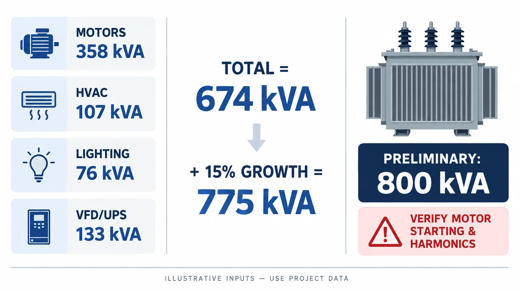
| Process motors | 420 kW | 0.88 | 0.75 | 420 ÷ 0.88 × 0.75 = 358 kVA |
| HVAC and pumps | 120 kW | 0.90 | 0.80 | 120 ÷ 0.90 × 0.80 = 107 kVA |
| Lighting and receptacles | 80 kW | 0.95 | 0.90 | 80 ÷ 0.95 × 0.90 = 76 kVA |
| VFD and UPS input loads | 150 kW | 0.96 | 0.85 | 150 ÷ 0.96 × 0.85 = 133 kVA |
| Maximum coincident demand | 674 kVA |
If the approved planning allowance is 15%:
674 kVA × 1.15 = 775 kVA
The preliminary selection is therefore the next available rating at or above 775 kVA. If an 800 kVA unit is available in the applicable product range, it is the first rating to evaluate—not an automatic final answer.
At 400 V, an 800 kVA transformer corresponds to approximately:
800 × 1000 ÷ (√3 × 400) = 1,155 A
The downstream switchboard, busbar, cables and protective devices must be reviewed for the selected transformer’s current and prospective short-circuit duty. The worked example also needs the following checks before 800 kVA can be accepted.
Checks that can change the selected kVA
Motor starting and voltage dip
A large direct-on-line motor can draw several times its running current during acceleration. The resulting transformer voltage drop can prevent acceleration, disturb contactors or affect other loads even when the steady-state kVA appears adequate.
Schneider Electric’s motor-transformer guidance relates estimated starting voltage drop to locked-rotor current, transformer secondary full-load current and transformer impedance. For a project study, use the actual motor starting current and acceleration time, starter or drive method, transformer impedance, upstream-source impedance, cable impedance and minimum acceptable voltage at the motor and other sensitive loads.
Do not permanently add locked-rotor kVA to the continuous load total. Treat starting as a time-dependent voltage-dip and thermal-duty case. The solution may be a larger transformer, a lower-impedance selection, reduced-voltage starting, a soft starter, a variable-speed drive, a changed starting sequence or a separate transformer—subject to system studies and protection coordination.
Harmonic and nonlinear loads
Variable-speed drives, UPS systems, rectifiers, EV charging, IT power supplies and other nonlinear loads draw nonsinusoidal current. Harmonics can increase winding and stray losses and can raise neutral current in four-wire systems. A simple kW divided by displacement power factor calculation may miss this effect.
Use equipment input data, true power factor, harmonic spectrum or measured current where available. Ask the transformer manufacturer to confirm suitability for the stated nonlinear-load profile, winding/conductor design, temperature-rise basis and any derating. Harmonic filters or multi-pulse/active-front-end solutions are system decisions; they should not be assumed from a transformer size alone.
Cyclic, intermittent and high-inrush loads
Welders, crushers, compressors, furnaces, lifts and batch processes may impose short peaks that are not represented by average demand. Record cycle duration, repetition, peak kVA and acceptable voltage variation. Thermal behavior and voltage regulation may lead to different conclusions, so the load profile matters.
Transformer energization is another transient. Inrush, protection settings and source strength must be coordinated, especially when multiple transformers are energized after an outage.
Ambient temperature, altitude and enclosure
Rated capability depends on stated service and cooling conditions. High ambient temperature, altitude, restricted ventilation, solar heating or installation inside an enclosure can affect temperature rise and available loading. Dry-type transformers also require coordinated airflow and enclosure performance.
IEC 60076-1 provides the general power-transformer framework, while technology-specific parts such as IEC 60076-11 address dry-type transformers. State the applicable standards, service conditions and enclosure arrangement and ask the manufacturer to identify any required adjustment.
Redundancy and operating philosophy
One transformer sized for the full peak is not the only architecture. Projects may use two transformers on separate bus sections, an N+1 arrangement or an emergency transformer for selected loads. The rating must be checked for every permitted operating state:
- normal split-bus operation;
- one transformer out of service;
- bus-coupler closed or open;
- emergency generation or alternate source;
- future parallel operation, if allowed.
Redundancy is not created merely by installing two units. The switchgear, protection, interlocking, fault level and permitted loading during a contingency must support the intended philosophy.
Impedance, losses and voltage regulation
Transformer impedance affects short-circuit current and voltage drop. Selecting a larger kVA can increase the available fault current on the LV bus, so downstream equipment ratings and protection coordination must be recalculated.
Compare no-load loss, load loss at the stated reference conditions, expected load profile and applicable efficiency requirements. A transformer with more spare kVA may operate at a lower load fraction, but lifecycle performance depends on the actual loss data and operating profile—not on capacity alone.
A practical sizing worksheet
Before requesting a quotation, capture these inputs in one controlled schedule:
| Section | Required information |
|---|---|
| Electrical system | Primary/secondary voltage, frequency, phases, earthing, source fault level |
| Load basis | Connected kW/kVA, true PF, efficiency, demand/coincidence factors, peak scenario |
| Dynamic loads | Largest motors, starting method/current/time, cyclic peaks, transformer inrush sequence |
| Power quality | Nonlinear-load share, harmonic spectrum or measurements, neutral loading |
| Planning | Confirmed future loads, growth allowance, initial and future operating cases |
| Architecture | Number of transformers, bus sections, contingency loading, parallel-operation rules |
| Site | Indoor/outdoor, ambient, altitude, ventilation, enclosure, access and noise limits |
| Transformer | Technology, rating, impedance, vector group, taps, losses, cooling and accessories |
| Interfaces | MV/LV connections, protection, metering, switchgear ratings and cable/busbar arrangement |
| Evidence | Applicable standards, datasheets, drawings, loss schedule, verification/test documents and deviations |
For the wider information package, use CANGO’s power transformer project-information guide. If the technology is still open, compare oil-immersed and dry-type transformers separately from capacity.
Common transformer-sizing mistakes
- Adding nameplate kW without converting mechanical output to electrical input.
- Treating connected load as maximum demand without an operating scenario.
- Using one assumed power factor for motors, drives, UPS systems and lighting.
- Applying unexplained diversity and growth percentages.
- Adding motor locked-rotor kVA as if it were a continuous load.
- Ignoring harmonics, cyclic duty, temperature, altitude or enclosure heating.
- Selecting kVA without checking impedance, fault level and downstream switchgear.
- Assuming two transformers automatically provide N+1 capacity.
- Choosing a catalog rating before confirming voltage, taps, vector group, cooling, losses and interfaces.
Review the preliminary rating with CANGO
CANGO’s power transformer category includes oil-immersed and dry-type distribution-transformer families. The S11-M oil-immersed family and SC(B)12 dry-type family illustrate different technology routes; their final capacities and specifications must match the project schedule.
For an industrial system view, see the industrial power distribution guide. Send the load schedule, operating cases, voltage combination, preliminary kVA, starting and harmonic information, site conditions, quantity and destination so the proposed transformer configuration can be reviewed against a common basis.