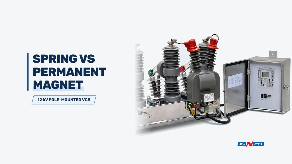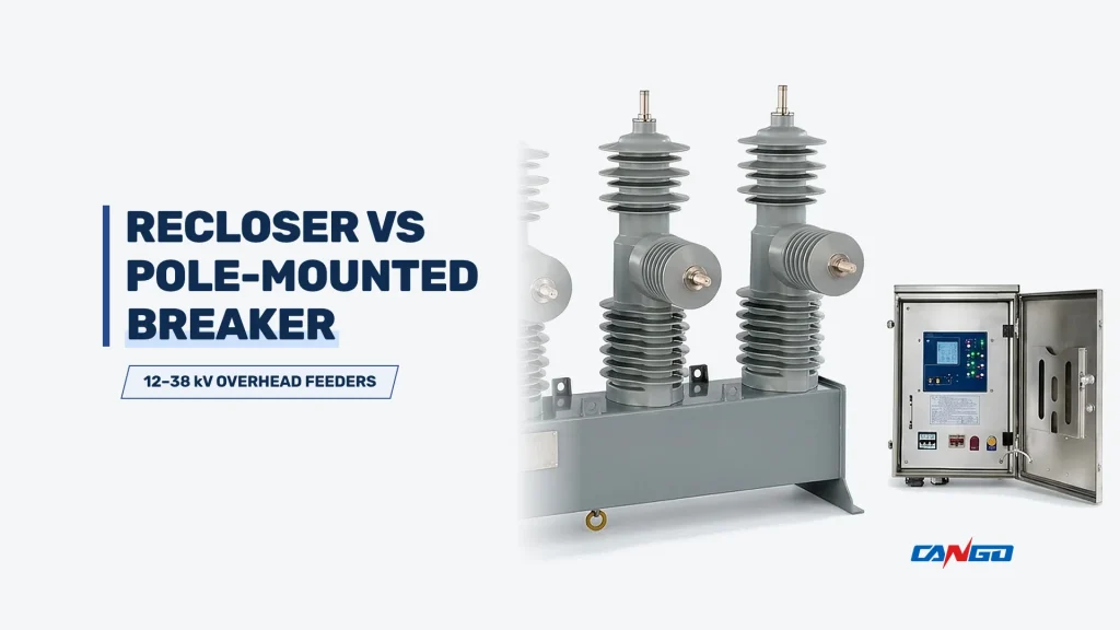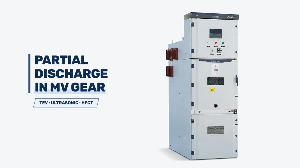
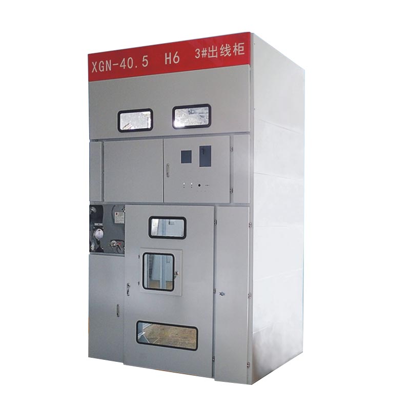
Two medium-voltage switchgear inquiries can have the same voltage requirement and still need different equipment arrangements. A clear inquiry describes the electrical duties, the operating arrangement and the installation interfaces together.
Define the function of each panel
Use a single-line diagram and a panel schedule to show incoming feeders, outgoing feeders, transformer circuits, metering and any bus-section arrangement. Identify the purpose of each panel rather than relying on a general request for a set of switchgear.
CANGO’s catalog includes several medium-voltage equipment families. The appropriate family depends on the project requirements; a model name alone does not define every panel’s components and functions.
A panel schedule should explain the electrical role of every position in the lineup. Start with circuit references that match the single-line diagram and state the source or load connected to each position. Separate equipment installed at delivery from space reserved for future panels. A request for a quantity of cabinets without circuit functions leaves the supplier to make assumptions about switching devices, instrument transformers, protection and auxiliary circuits.
The example functions below are a planning framework, not a mandatory configuration. An incoming panel connects a source to the bus; an outgoing panel supplies a downstream circuit; a transformer feeder must be reviewed with the transformer protection arrangement. Metering and bus-section functions need their own defined scope. Whether functions are combined or separated in particular equipment depends on the selected family and project requirements.
For each panel, distinguish the requested primary function from the required secondary interfaces. State whether the project requires local control, remote operation, specified indications or interlocking with another panel. Identify the documents that define the operating philosophy. Do not assume that two panels with the same voltage and current need the same control scheme. Ask the proposal to return the completed panel schedule so omissions can be identified before detailed drawings are reviewed.
| Illustrative panel function | Describe in the schedule | Interface to identify |
|---|---|---|
| Incoming | Source reference and bus connection | Source protection, control and metering responsibilities. |
| Outgoing | Connected cable/load and circuit role | Downstream protection and required remote signals. |
| Transformer feeder | Transformer reference and protection concept | Transformer data and switching/protection coordination. |
| Metering | Required measurements and specified arrangement | Utility/customer requirements and secondary connections. |
| Bus section/coupler | Required bus operating arrangement | Interlocks and permitted source operating states. |
Keep the ratings separate
Rated voltage, normal current and short-circuit duties describe different requirements. Record the values required by the project engineer or utility, including the relevant duration where a short-time withstand rating is specified. Do not use a normal-current value as a substitute for fault-duty information. Manufacturer switchgear comparisons list these as separate characteristics; see ABB’s air-insulated switchgear overview for general background.
Write the required ratings as separate entries with their source and applicable conditions. The network nominal voltage, equipment rated voltage, normal current and fault duties answer different questions. Include the frequency and the required insulation information from the project specification. Where a rating is subject to utility confirmation, identify that status. A catalog family name should not be used to fill missing requirements by assumption.
Current requirements also need a location. Distinguish the main busbar duty from the incoming device and individual outgoing circuits. Identify the applicable short-time withstand requirement and duration, and keep peak or making duties separate from breaking duties. Copy the project wording accurately and ask the supplier to explain the corresponding offered rating. Do not translate between unlike duties using an undocumented rule of thumb.
Service conditions and enclosure requirements belong beside the electrical data. State indoor or outdoor installation, project ambient conditions and the specified protection level. Unusual conditions should be reviewed against manufacturer data for the selected configuration. A rating accepted for one installation condition does not automatically establish suitability for another. The supplier response should identify any limitations, alternatives or information still required before the selection is confirmed.
| Rating group | Information required | Comparison check |
|---|---|---|
| Voltage/insulation | Project voltage, frequency and specified insulation duties | Keep network designation and equipment rating distinguishable. |
| Continuous current | Busbar and circuit-specific required currents | Compare the same circuit and service conditions. |
| Fault duties | Breaking, making and withstand requirements with duration where specified | Do not substitute one duty for another. |
| Enclosure/service | Location, environment and protection requirements | Confirm the offered arrangement against the installation specification. |
Confirm control and protection interfaces
State the required auxiliary supply, metering, protection and communication interfaces. If specific relays or components are required, include the project specification. Identify which settings, studies and site interfaces are supplied by the project team and which documents are expected from the equipment supplier.
Prepare a secondary-interface list alongside the primary panel schedule. Identify the required control supply and the party providing it, the necessary protection and metering functions, the external signals and the communications interface. Separate a requirement for a device from the requirement for a fully integrated scheme. The presence of a protection relay or communications port does not define its settings, logic or relationship to other project systems.
For every exchanged signal, identify the originating equipment, receiving system and purpose. Where the project requires remote commands, identify the operating permissions and interlocks to be reviewed. Record responsibility for wiring outside the lineup and for configuring the supervisory system. A signal list should distinguish monitoring from commands rather than treating every connection as a generic communications item.
Protection studies, settings approval and commissioning responsibilities must be allocated explicitly. If the project specifies particular relays or instrument-transformer requirements, send the relevant documents and revisions. Ask the supplier to flag a conflict between the relay schedule and the primary-circuit specification. Final settings and integration should be confirmed through the project process; a quotation response does not by itself approve a protection design.
| Interface | List in the inquiry | Allocate responsibility |
|---|---|---|
| Auxiliary power | Required control supply and relevant project constraints | Supply source and connections outside the lineup. |
| Protection/metering | Functions, specified devices and measurement requirements | Studies, settings, approval and equipment documents. |
| Signals/communications | Status, alarms, commands and receiving system | External wiring, configuration and integration testing. |
| Interlocking | Permitted and prohibited operating states | Review with the complete operating philosophy. |
Include physical constraints
- Indoor or outdoor installation and the available equipment-room layout.
- Cable entry direction and the available termination space.
- Operating and maintenance access requirements.
- Existing equipment interfaces for an extension or replacement.
- Environmental and enclosure requirements stated in the project specification.
For a retrofit, photographs are useful alongside dimensions, existing drawings and nameplate information. They help explain the installation, but should not replace verified technical data.
Provide an annotated room plan with the available lineup position, access doors and cable routes. Identify operating and maintenance faces and any restrictions on rear access. Show adjacent equipment that affects doors, cable handling or extension. The purpose is to allow the supplier to review the arrangement against the actual installation, not simply to demonstrate that the sum of cabinet widths fits along a wall.
Cable interfaces should be described with entry direction, termination requirements and known constraints at the cable trench or basement. For a retrofit, include existing drawings and verified dimensions, together with photographs that explain the condition. Mark dimensions that have not been surveyed. A photograph is useful context but should not be converted into a manufacturing dimension without confirmation.
Consider delivery and future replacement as well as first installation. Identify the route from site entry to the equipment room, known handling restrictions and how shipping sections can reach their positions. Where future extension is required, specify its intended side and the information available about the existing interface. Final clearances, handling and installation methods must follow the selected manufacturer documentation and coordinated project drawings; do not adopt generic distances from an unrelated assembly.
| Physical check | Information to supply | Review outcome |
|---|---|---|
| Room arrangement | Plan, operating faces and adjacent equipment | Confirm access and proposed lineup arrangement. |
| Cable interface | Entry direction, trench location and termination constraints | Coordinate cabinet and cable layouts. |
| Delivery | Access route and handling restrictions | Review shipping sections and installation responsibilities. |
| Extension | Existing equipment and intended connection side | Review compatibility rather than assuming interchangeability. |
Agree what the quotation includes
Ask for a defined panel list, equipment configuration, document list and stated exclusions. Any provisional item should be visible in the quotation. This makes it easier to compare offers and resolve differences before production planning.
Browse CANGO medium-voltage switchgear and our retrofit and expansion guide. For a real installation reference, see the Tianjin Chengxi distribution renovation project.
REVIEW YOUR SWITCHGEAR REQUIREMENTS ↗
Ask suppliers to separate the equipment configuration, documents and services in their response. The primary device schedule, secondary equipment, accessories and shipping arrangement should be identifiable. If particular documents or project reviews are required, list them explicitly rather than relying on an undefined promise of a complete technical package. The same applies to site attendance, external cabling and commissioning activities.
A compliance schedule should show the requirement, the offered arrangement and any deviation or clarification. Request alternatives in a separate section so a different switchgear family or circuit arrangement is not mistaken for an identical offer. Record whether drawings are quotation-stage information or documents intended for approval before manufacture. This makes the level of design definition clear to purchasing and engineering reviewers.
The inclusion/exclusion worksheet below does not establish a standard CANGO contract. It is a set of questions to resolve with the selected offer. Review both explicit exclusions and unmentioned interfaces. An item missing from a response should be clarified before an order rather than assumed to be included because it is necessary somewhere in the project. Maintain the accepted clarification record with the final equipment schedule.
| Scope question | Included response to request | If outside the offer |
|---|---|---|
| Primary/secondary equipment | Identified configuration and accessories | Name the party supplying missing equipment. |
| Documents | Specified drawings, schedules and verification records | Agree who supplies other required design documents. |
| Site interfaces | Defined termination, signal and installation boundaries | Allocate external wiring and integration work. |
| Services | List any included project or site activities | Identify the separately arranged scope and approvals. |
Build a panel schedule that suppliers can compare
Prepare a separate entry for every panel function. An incoming feeder, transformer feeder, metering panel and bus-section panel can have different requirements even within one lineup. Give each circuit a reference matching the single-line diagram. State which circuits are required now, which are future extensions and whether spare space means a fitted panel or only a reserved location.
List protection and control responsibilities alongside the primary circuit. Distinguish the required relay functions and interfaces from the settings or coordination study. Identify who supplies and approves settings, who provides auxiliary power and who integrates communications. A reference to a relay brand does not answer all of these questions.
For an extension, provide existing switchgear drawings and interface details rather than assuming that equipment of the same voltage class is interchangeable. The busbar interface, physical arrangement, interlocking and operating requirements need review. Mark any shutdown or access constraint that affects the installation plan, while keeping site work distinct from the equipment supply.
For an illustrative comparison, imagine a lineup containing incoming, outgoing, transformer, metering and bus-section functions. The buyer sends the same circuit references and requirements to each supplier. Each supplier returns its proposed arrangement against those references, even if the physical combination of functions differs. This allows reviewers to compare the electrical scope without assuming that equal cabinet counts mean equal functionality.
Use the comparison to expose omissions rather than to force identical wording. If an offer combines functions, ask it to identify how the stated requirements are covered. If it reserves space instead of supplying a fitted future circuit, mark that distinction. Keep the busbar and circuit duties, protection scope and document requirements visible alongside the panel list. Review any change with the project engineer before accepting the commercial comparison.
The final schedule should link each accepted circuit to the relevant drawing revision and any approved deviation. Outstanding protection, control or site information remains in the clarification register until resolved. If the design changes, update all affected suppliers or identify the offer revision being compared. This prevents procurement from comparing one supplier against an earlier configuration while another has included the latest design changes.
| Comparison entry | Required reference | What to reconcile |
|---|---|---|
| Circuit identity | Same single-line diagram reference | Function included, combined or omitted. |
| Installed versus future scope | Fitted equipment and reserved positions | Do not count empty space as a complete circuit. |
| Configuration revision | Schedule, drawings and deviation list | Ensure every offer reflects the same issued basis. |
| Approval status | Confirmed requirements and open items | Separate quotation review from manufacturing release. |
Inquiry review checklist
| Review area | Information to provide | Decision to confirm |
|---|---|---|
| Panel function | Circuit reference, incoming/outgoing role and connected equipment | Align the panel schedule with the single-line diagram. |
| Electrical duty | Project voltage, normal current and fault-duty requirements | Keep different ratings and their specified durations separate. |
| Secondary systems | Auxiliary supply, protection, metering and signals | Allocate settings, studies and integration responsibilities. |
| Installation | Cable entries, access, extension and existing interfaces | Review general arrangement and termination requirements. |
Use a compliance schedule when comparing proposals: requirement, offered arrangement, deviation and clarification required. Review alternatives as alternatives, rather than silently replacing the specified arrangement. Before order release, reconcile the panel list, drawings and component schedule and retain a written record of agreed deviations. The quotation is an input to this review, not a substitute for approval of the installation design.
Related reading
- Medium-Voltage Switchgear: Types, Ratings and Selection Guide
- Medium Voltage Switchgear Maintenance: Inspection Checklist and Intervals
FAQ
Is the rated voltage enough to choose switchgear?
No. The inquiry also needs circuit functions, normal-current and fault-duty requirements, control interfaces, site conditions and physical constraints. A voltage class alone does not define a complete lineup.
Should every panel use the same configuration?
Specify the function of each panel on the single-line diagram and panel schedule. Incoming, outgoing, transformer and metering circuits should be reviewed against their individual duties.
Who should provide protection settings?
The inquiry should allocate responsibility for settings, studies and approvals. Describe the supplier documents and site interfaces required instead of assuming that specifying a relay includes the complete protection study.
What is needed for a switchgear extension?
Provide existing drawings, dimensions, nameplate data and interface information. Explain operating and access restrictions so the busbar, physical and control interfaces can be reviewed.
How can I compare quotations consistently?
Use the same panel schedule and drawing revision, then compare offered ratings, components, documents, exclusions and deviations. Close provisional points before treating the proposal as a manufacturing specification.
References
- CANGO Power, Medium-Voltage Switchgear Portfolio (CANGO product category information).