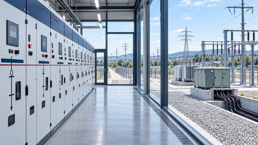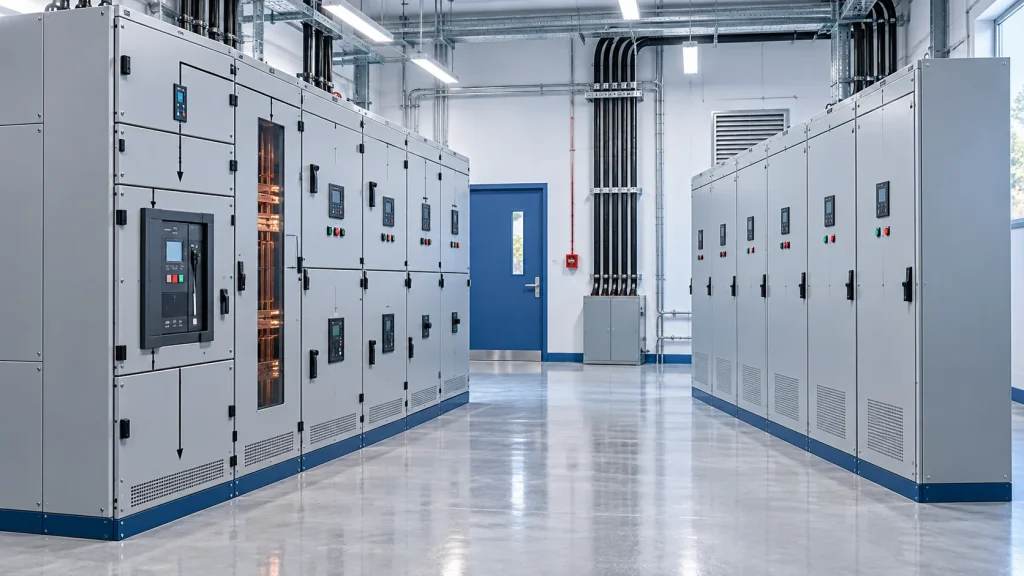
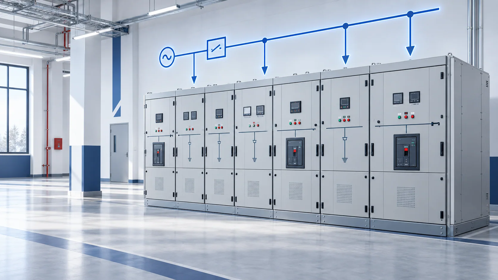
A medium-voltage switchgear single-line diagram, or SLD, is a simplified map of the primary electrical path. It shows how sources, busbars, switching devices, instrument transformers and outgoing circuits relate to one another without drawing all three phases or every control wire.
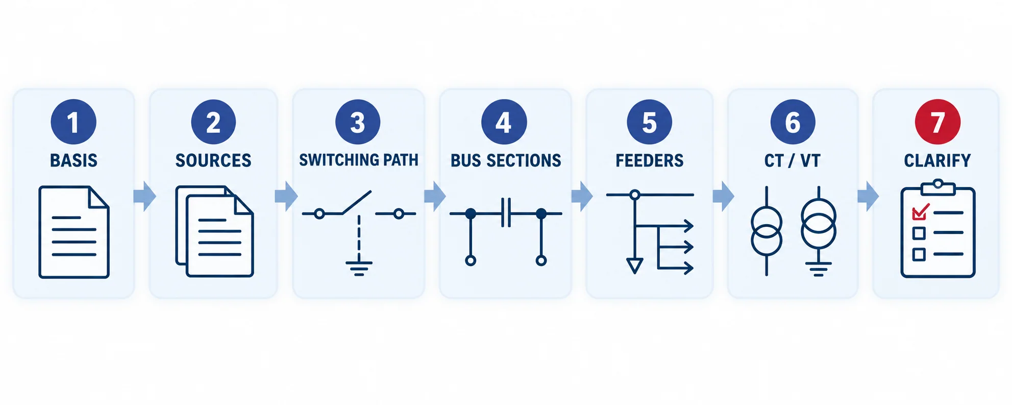
The quickest way to read one is to trace the system from source to load in seven passes: confirm the drawing basis, find the source, follow the main switching path, identify bus sections, classify each feeder, locate measurement and protection inputs, and record everything the drawing does not specify.
An SLD is a design and communication document. It is not a switching instruction, a complete protection schematic or proof that a proposed assembly meets every project rating.
What an MV switchgear single-line diagram shows
An SLD reduces a three-phase system to one representative line. On an MV switchgear drawing, it usually communicates four things:
- Topology: which source feeds which bus and which bus supplies each circuit.
- Functional units: incomers, outgoing feeders, bus couplers, risers, metering units and transformer or motor feeders.
- Primary devices: circuit breakers, disconnectors, load-break switches, fuses, earthing switches, current transformers and voltage transformers.
- Reference information: equipment tags, ratings, cable or transformer references, relay references and cross-links to schedules or other drawings.
The symbol library and drawing convention matter. The IEC 60617 database is the IEC source for graphical symbols used in electrotechnical diagrams, but real project drawings also use client-specific tags, abbreviations and CAD libraries. Always read the project legend before assigning meaning to an unfamiliar symbol.
Start with the drawing basis, not the first symbol
Before tracing power flow, read the title block, legend, revision, notes and drawing references. Confirm:
- the system voltage and frequency;
- whether the diagram is existing, proposed, tender or as-built;
- the normal operating condition, if stated;
- the applicable symbol convention;
- the boundaries between utility, owner, EPC and equipment-supplier scope;
- references to the load schedule, protection study, cable schedule, panel schedule and secondary schematics.
Revision control is important. A technically clear drawing can still be the wrong basis if its issue status does not match the project stage.
A seven-pass method for reading the SLD
1. Find every source
Locate utility incomers, upstream substations, generators, transformers or alternate supplies. Record the source tag and the point where each source enters the switchgear. Do not assume that two sources are permitted to operate in parallel merely because both appear on the page.
2. Follow the main switching path
Trace each source through the primary switching device toward the busbar. A circuit-breaker feeder may also show disconnecting or isolating functions, current transformers, an earthing switch and cable terminations. The exact order and implementation depend on the offered equipment and drawing convention.
3. Divide the bus into sections
A long horizontal line commonly represents a busbar. Look for section labels, rated-current notes and the device that joins two sections. A bus coupler or bus-tie breaker connects bus sections. A riser may provide the conductor path between a breaker panel and the adjacent bus section.
The drawn device position does not always state the normal operating state. Look for text such as “normally open,” “normally closed,” an operating philosophy note or a separate switching schedule.
4. Classify each outgoing circuit
Follow every vertical branch away from the bus. Its destination may be a transformer, motor, downstream switchboard, capacitor bank, station service circuit or cable feeder. Match each feeder tag to the load or cable schedule. A generic outgoing arrow without a destination is not enough for final lineup definition.
5. Locate measurement inputs
Identify current transformers and voltage transformers, often called CTs and VTs or PTs. Their position tells you what part of the system is being measured, but the symbol alone does not establish ratio, accuracy class, burden, protection class, core count or secondary arrangement.
6. Locate protection and control references
A relay box, device-function number or drawing reference may show which protection functions use the CT and VT signals. Treat that information as a pointer to the protection schematic and study. The SLD rarely contains the complete trip logic, interlocks, communications, auxiliary supply or terminal wiring.
7. Mark missing decisions
Create a clarification list while reading. Typical gaps include fault duty, normal operating state, CT/VT data, cable entry, feeder destination, transformer data, earthing arrangement, auxiliary voltage, interlocking, SCADA scope and future extension.
Common functional units and what they mean
Manufacturer catalogues illustrate how the same basic symbols form different functional units. The ABB UniGear ZS1 technical catalogue includes typical single-line diagrams for incoming/outgoing feeders, bus ties, risers and measurement units. These examples are useful for learning, but the project legend and offered assembly remain authoritative.
| Functional unit | What to look for on the SLD | What still needs confirmation |
|---|---|---|
| Incomer | Source reference, primary switching device and connection to the main bus | Source fault level, normal state, protection, interlocks and cable or busduct interface |
| Outgoing feeder | Branch from the bus to a named load or downstream node | Load duty, cable data, breaker or switch duty, CTs, protection and termination |
| Bus coupler / bus tie | Device connecting two labeled bus sections | Normally open/closed state, transfer philosophy, interlocking and parallel-operation limits |
| Riser | Conductor path joining a device or section to the bus | Physical panel arrangement and whether measurement devices are included |
| Metering / VT panel | VT/PT connection to a bus or feeder, sometimes with isolation and fusing | Ratio, accuracy, burden, protection, isolation method and secondary distribution |
| Transformer feeder | Feeder terminating at a transformer symbol or reference | Transformer rating, vector group, impedance, inrush duty, protection and cable interface |
| Earthing function | Earthing-switch symbol or earth connection associated with a circuit | Rated duty, interlocks, location, access procedure and project safety rules |
IEC 62271-200 applies to prefabricated AC metal-enclosed assemblies above 1 kV and up to and including 52 kV. An SLD can define the required functions of that assembly, but it does not by itself demonstrate that a specific design has the required ratings, classifications or test evidence.
Worked example: a double-ended switchgear lineup
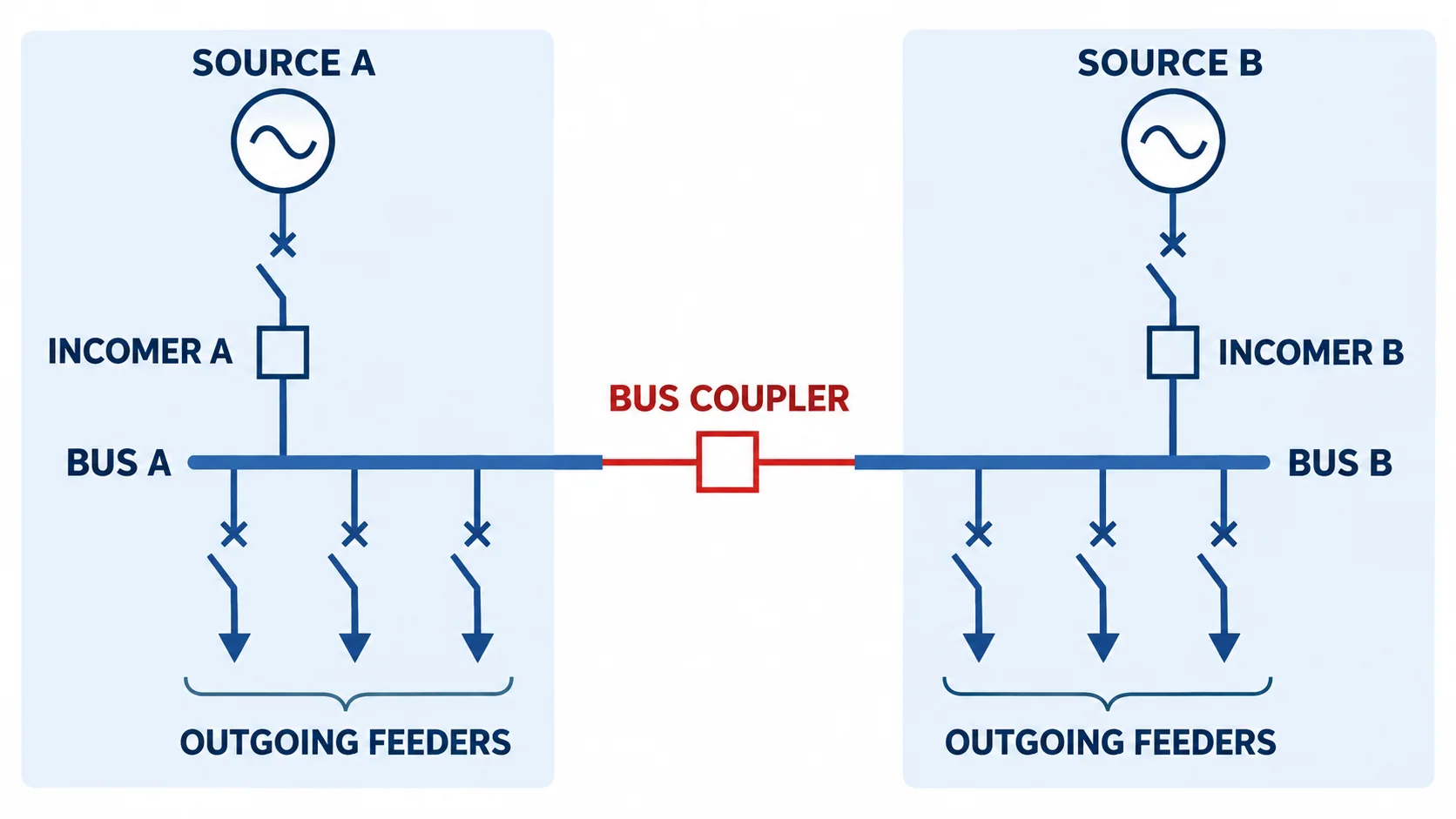
Consider a lineup with Source A and Source B, two incomer breakers, Bus A, Bus B and a bus-coupler breaker between the sections. Each bus has outgoing feeders.
Read it in this order:
- Source A to Incomer A: confirm where the first source originates and whether its incomer is expected to be closed in normal service.
- Incomer A to Bus A: note the bus section supplied and the incoming measurement/protection devices.
- Source B to Incomer B: repeat the same checks for the second source.
- Incomer B to Bus B: verify that feeder tags and bus labels remain consistent across drawing pages.
- Bus coupler: determine whether it is normally open, normally closed or controlled by an automatic transfer scheme. The symbol alone cannot answer this.
- Outgoing feeders: trace every branch to its destination and compare it with the load and cable schedules.
- Operating cases: check normal, maintenance and contingency states against the short-circuit and protection studies.
If the two sources can be paralleled, fault level, transformer compatibility, synchronizing, protection and utility rules may change. Never infer permission to parallel from the physical presence of a coupler.
How to interpret CTs and VTs/PTs
Current and voltage transformers connect the primary system to measuring and protective equipment. IEC 61869-2 covers additional requirements for current transformers, while IEC 61869-3 addresses inductive voltage transformers.
Current transformers
CT placement helps identify the protection zone and measurement point. CTs on the cable side of an incomer do not represent the same electrical boundary as CTs on the bus side. A group marked “3” may indicate one CT per phase, but the project notation must confirm this.
The SLD may show a CT ratio or relay reference. Detailed selection still requires the number and purpose of cores, ratios, metering and protection classes, burden, transient or saturation requirements, polarity and secondary terminal plan.
Voltage transformers or potential transformers
A VT/PT connected to the bus measures bus voltage. A feeder-side VT measures that feeder or source point. Its location affects metering, protection, synchronizing and voltage-supervision functions.
Confirm whether the VT is fixed, withdrawable or otherwise isolatable, how its primary and secondary circuits are protected, and where the secondary voltage is distributed. A simple branch symbol cannot establish these construction details.
What the SLD does not prove
The single-line diagram should be read with schedules and specifications. It normally cannot prove all of the following on its own:
| Topic | Required supporting document or data |
|---|---|
| Rated voltage, insulation level and frequency | Project specification and equipment datasheet |
| Normal current and busbar current | Load schedule, diversity basis and panel schedule |
| Short-circuit breaking and withstand duties | Short-circuit study and equipment compliance schedule |
| CT/VT performance | Instrument-transformer schedule and protection/metering design |
| Relay functions and settings | Protection philosophy, coordination study and relay settings file |
| Interlocks and trip logic | Control schematic, logic diagram and cause-and-effect documentation |
| Cable and termination arrangement | Cable schedule, termination details and general-arrangement drawing |
| LSC, IAC and enclosure classifications | Project specification and verified assembly documentation |
| Physical access and room interfaces | General arrangement, room layout and civil/interface drawings |
| Safe switching sequence | Approved operating procedure and site-specific switching program |
This distinction prevents a common review error: treating a clean diagram as evidence that all technical decisions are complete.
Review checklist for engineering and procurement
Before using an SLD to request or compare switchgear offers, check that it answers these questions:
- Are all sources, bus sections and feeder destinations named?
- Are normal operating states and permitted transfer or parallel conditions stated?
- Does every panel function map to a panel schedule?
- Are circuit-breaker, load-break switch, disconnector, fuse and earthing functions distinguishable?
- Are CT and VT/PT locations shown and their detailed schedules referenced?
- Are system voltage, frequency, earthing method and fault duties available elsewhere in the package?
- Are transformer, motor and capacitor-bank feeders identified by actual duty?
- Are future panels, spare ways and extension directions clear?
- Are protection, control, auxiliary supply and communication drawings referenced?
- Are the issue status, project standard, supply boundary and required deliverables clear?
Use the medium-voltage switchgear selection guide for the broader equipment decision. Then use the quotation checklist to turn the SLD and schedules into a comparable inquiry package.
From diagram review to equipment discussion
CANGO’s medium-voltage switchgear category includes KYN28-12, KYN28-24 and KYN61-40.5 families as well as compact and ring-main equipment. A model family can frame the discussion, but the final lineup must follow the project SLD, panel schedule, ratings, protection interfaces and site conditions.
For wider application context, see the industrial power distribution solution. When requesting a technical review, provide the latest SLD together with the load list, short-circuit data, equipment schedule, applicable standards and a list of unresolved interfaces.