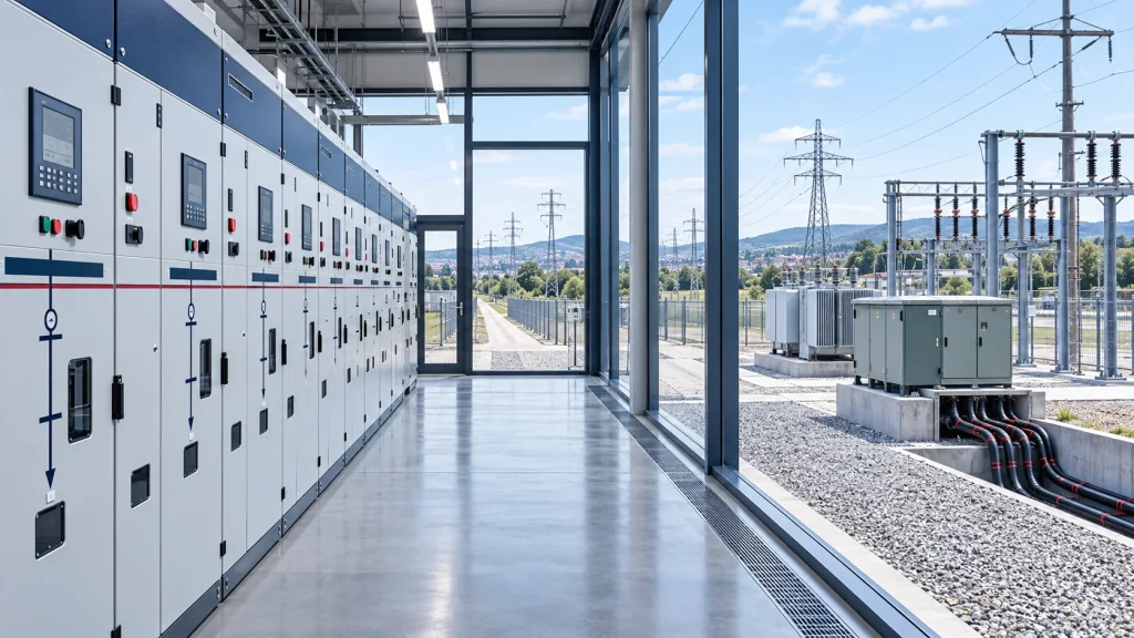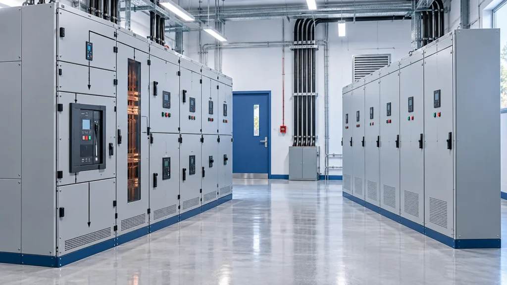
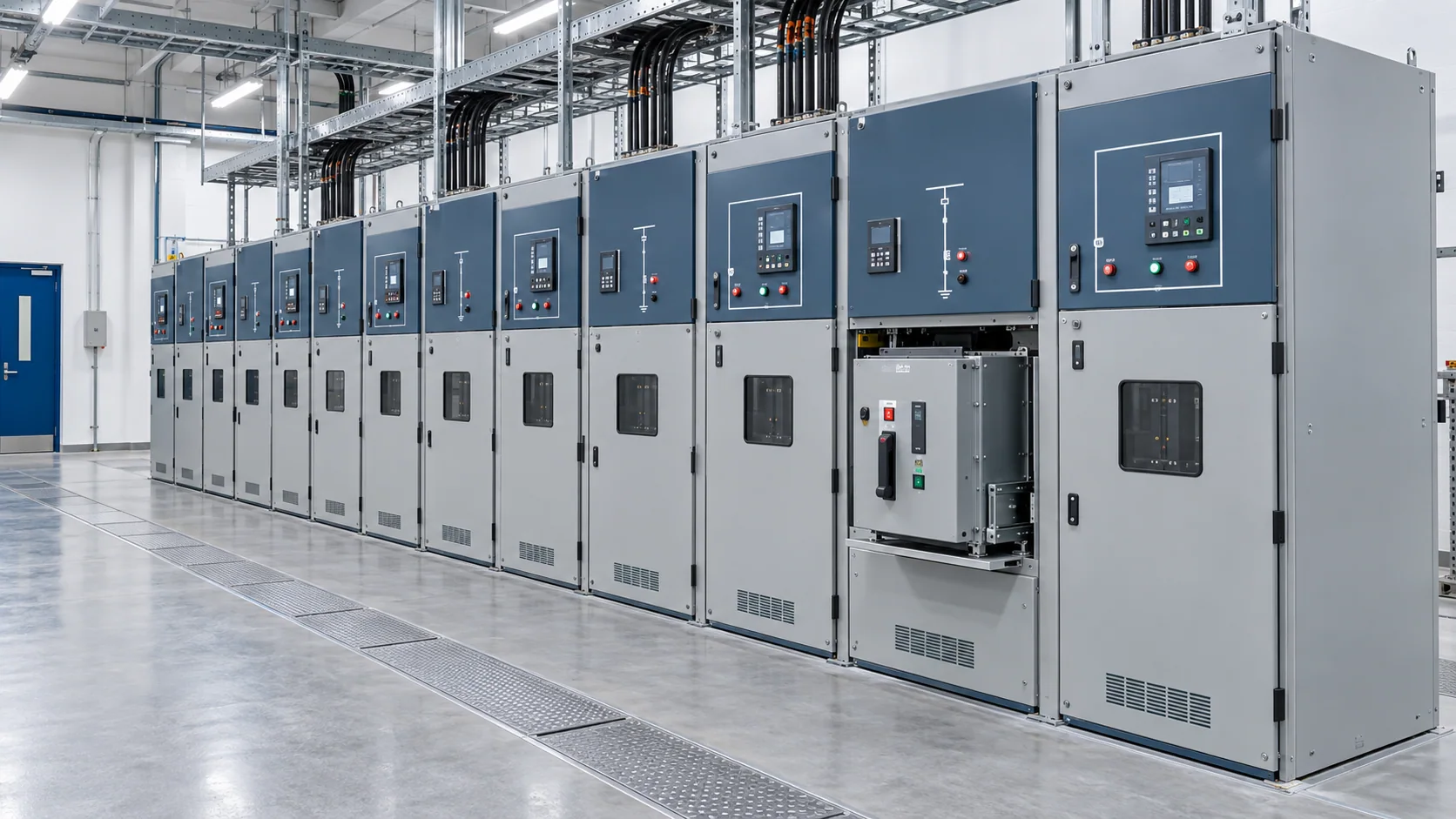
Medium-voltage switchgear should be selected from the electrical duty and operating plan, not from voltage class or a familiar model name alone. A defensible selection aligns the system voltage, continuous current, short-circuit duty, insulation level, feeder functions, service-continuity requirements, internal-arc specification, site conditions and protection interfaces.
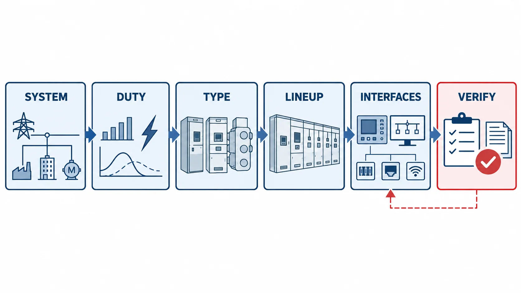
For project buyers, the practical sequence is straightforward: define the system, calculate or obtain the fault duty, choose an appropriate construction family, build the required panel lineup, and compare only offers that state the same ratings, classifications, tests and supply boundaries.
What medium-voltage switchgear means in an IEC project
Medium-voltage switchgear is an assembly of switching, protection, measurement, control and connection functions used to receive and distribute electrical power. A lineup may contain incoming panels, outgoing feeders, bus sections, transformer feeders, motor feeders, metering panels and voltage-transformer compartments.
The terminology can look inconsistent. The commercial power-distribution market commonly calls equipment in this range “medium voltage,” while the title of IEC 62271-200 uses “high-voltage switchgear and controlgear.” Its scope covers prefabricated AC metal-enclosed assemblies with rated voltages above 1 kV and up to and including 52 kV for indoor or outdoor installation. IEC terminology therefore does not mean that ordinary 12 kV or 24 kV distribution switchgear should be described as transmission-class equipment in project copy.
IEC 62271-1 provides common specifications for AC switchgear and controlgear above 1,000 V. The project specification should identify the applicable edition, amendments and any utility or national requirements rather than relying on the standard number alone.
The main medium-voltage switchgear types
Several classification layers are often mixed together. Insulation medium, switching device, compartment arrangement and service application describe different aspects of the equipment.
| Selection layer | Common options | What it changes |
|---|---|---|
| Insulation arrangement | Air-insulated, gas-insulated or other enclosed dielectric systems | Footprint, environmental exposure, inspection approach and technology-specific requirements |
| Switching function | Circuit breaker, load-break switch, switch-fuse combination, disconnector and earthing switch | Which normal-load and fault duties the functional unit can perform |
| Primary-device arrangement | Withdrawable/removable or fixed | Isolation method, maintenance workflow, compartment arrangement and lineup design |
| Network role | Primary distribution switchgear, secondary distribution switchgear or ring main unit | Feeder duty, protection complexity, current/fault requirements and expansion strategy |
| Installation | Indoor or outdoor enclosure | Weather protection, room or enclosure interfaces, access and environmental design |
Withdrawable air-insulated switchgear
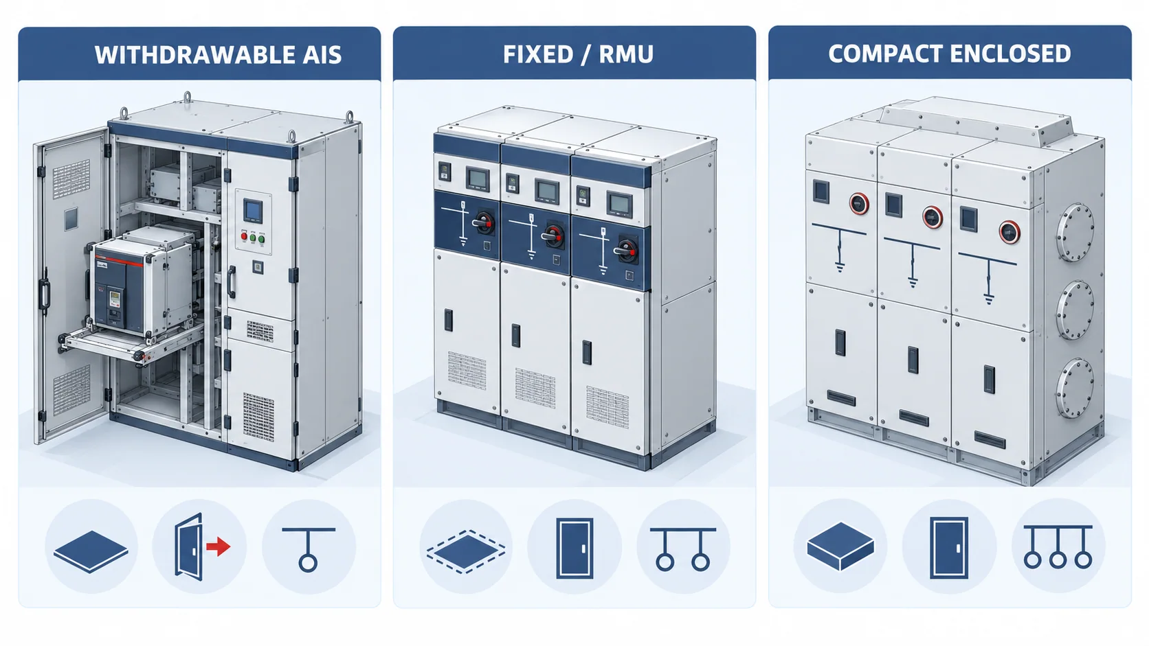
Withdrawable air-insulated metal-enclosed switchgear is widely considered for primary distribution where projects require circuit-breaker feeders, defined compartments and a maintenance strategy based on removable switching devices. It can support complex protection, metering and bus-section schemes, but the actual accessibility, partitioning and service-continuity category must come from the offered assembly.
Fixed metal-enclosed switchgear and ring main units
Fixed switchgear and ring main units are often used for secondary distribution, cable networks, transformer supply and compact distribution nodes. Depending on the functional unit, switching may be performed by a load-break switch, switch-fuse combination or circuit breaker. “RMU” does not define every rating or protection function; buyers still need a module schedule and verified duty for each way.
Gas-insulated and other compact enclosed systems
Gas-insulated or solid-/sealed-insulation arrangements place more of the primary circuit inside a controlled enclosure. They may be useful where footprint or environmental exposure is a major constraint. Air-insulated switchgear remains a modular option for many primary and secondary distribution applications. Manufacturer guidance from ABB’s medium-voltage overview likewise treats space, location, environment and project requirements as selection inputs rather than declaring one technology universally preferable.
Ratings buyers must keep separate
A frequent procurement error is to treat one large number as proof that a switchgear offer meets the complete duty. Every important rating answers a different engineering question.
| Rating or classification | The question it answers | Buyer check |
|---|---|---|
| Rated voltage | What equipment voltage class is the assembly designed for? | Match the system highest voltage and project insulation coordination—not only nominal operating voltage |
| Rated insulation level | What specified power-frequency and impulse withstand levels apply? | Confirm phase-to-earth, phase-to-phase and across-isolation requirements where applicable |
| Rated normal current | What current can the busbar or functional unit carry under stated conditions? | Check busbar, incomer and feeder ratings separately; account for ambient, enclosure and ventilation assumptions |
| Rated short-circuit breaking current | What fault current can the circuit breaker interrupt under its specified conditions? | Use the fault study and breaker duty; do not substitute a withstand-current value |
| Rated short-time withstand current | What RMS fault current can the main circuit withstand for a stated duration? | Compare both kA and duration, and confirm the complete current path |
| Rated peak withstand current | What peak current can the assembly withstand mechanically? | Check consistency with the specified short-circuit duty and system standard |
| Rated frequency | What system frequency is the equipment designed for? | State 50 Hz or 60 Hz as required by the project |
| Internal arc classification | What tested internal-arc arrangement and accessibility apply? | Specify required sides, accessibility type, current and duration; verify the offered test evidence and installation conditions |
| Loss of service continuity category | What other compartments or functional units are intended to remain energized when access is provided? | Match the maintenance and operating plan; verify the exact assembly category |
| Degree of protection | What enclosure protection is required for the installed condition? | Separate external enclosure needs from compartment-specific requirements and confirm the project environment |
Normal current, breaking current and short-time withstand current are not interchangeable. A 1,250 A feeder designation, for example, says nothing by itself about the prospective short-circuit current that the breaker must interrupt or the duration for which the assembly must withstand a fault.
Service conditions matter as well. Altitude, ambient temperature, humidity, condensation, dust, salt, corrosive atmosphere and room ventilation can change the required design or rating basis. State abnormal service conditions explicitly and require the supplier to identify any derating or special provisions.
Build the lineup from functional units
The single-line diagram should drive the panel schedule. Start by assigning a function to every cubicle or module:
- Incoming feeder: connects the source to the busbar and normally carries the protection, control and interlocking required by the supply arrangement.
- Outgoing feeder: supplies a downstream transformer, motor, substation or distribution circuit.
- Bus section or bus coupler: divides or connects bus sections according to the operating and redundancy philosophy.
- Metering or voltage-transformer panel: supports voltage measurement, metering, protection and synchronizing functions where required.
- Transformer feeder: coordinates switching and protection with transformer duty and the project protection study.
- Motor feeder: may require motor-specific switching, starting and protection consideration rather than a generic distribution-feeder assumption.
- Earthing and cable functions: establish how circuits are isolated, earthed, tested and accessed under the approved operating procedure.
The same voltage class can therefore produce very different lineups. A utility ring network, an industrial double-ended substation and a plant motor bus do not have identical feeder duties or continuity requirements.
IEC classifications belong in the selection, not as afterthoughts
IEC 62271-200 addresses metal-enclosed assemblies and includes classification concepts such as loss of service continuity and internal arc classification. These labels are not marketing grades.
Loss of service continuity, or LSC, describes the intended ability to keep other high-voltage compartments or functional units energized when access is provided to an accessible high-voltage compartment. Schneider Electric’s LSC explanation summarizes this operating consequence. Buyers should specify the maintenance scenario they need and then verify the exact category on the offered assembly.
Internal arc classification, or IAC, also needs a complete statement. A request that says only “arc resistant” is incomplete. The project team should define the required accessibility arrangement, accessible sides, fault current, duration, installation conditions and pressure-relief interface, then review applicable test evidence for the exact assembly or validated design.
Neither LSC nor IAC replaces safe operating procedures, protection coordination, arc-flash assessment or site-specific room design. They describe particular assembly characteristics and test conditions.
A six-step medium-voltage switchgear selection process
1. Define the electrical system
Record nominal and highest system voltage, frequency, earthing arrangement, source configuration, transformer data and normal operating modes. Include future bus ties, alternate sources and expansion plans.
2. Establish load and fault duties
Prepare the load schedule and obtain the short-circuit study at each switchgear bus. State continuous currents, prospective fault current, required clearing duration and any duty affected by motors, generators or parallel sources.
3. Choose the technology and device arrangement
Compare air-insulated, compact enclosed-insulation and RMU solutions against space, environment, network role, expansion, maintenance access and lifecycle support. Decide whether the project needs withdrawable circuit breakers, fixed devices, load-break switches, switch-fuse modules or circuit-breaker modules by feeder function.
4. Build the functional lineup
Translate the single-line diagram into incomers, feeders, bus sections, metering and auxiliary panels. Confirm busbar arrangement, cable entry, termination type, panel sequence, future extension direction and transport splits.
5. Define protection, control and communication interfaces
State protection philosophy, instrument transformers or sensors, metering, auxiliary supplies, trip/close circuits, interlocks, local/remote control, SCADA protocol, time synchronization and required terminal interfaces. Protection settings and system studies remain project-engineering tasks unless explicitly included in the supplier scope.
6. Verify classifications, tests and documents
List applicable standards and required classifications. Request a compliance schedule, general-arrangement drawing, single-line and schematic drawings, datasheets, type-test evidence where required, routine-test documentation, manuals, spare-parts list and clear exclusions. Compare offers only after deviations and provisional items are visible.
Selection matrix by project condition
| Project condition | Shortlist emphasis | Verify before selection |
|---|---|---|
| Primary industrial or utility distribution | Circuit-breaker feeders, bus arrangement, protection and service continuity | Fault duty, breaker rating, LSC/IAC requirement, relay interfaces and expansion plan |
| Cable ring or compact secondary distribution | RMU module functions and compact arrangement | Load-switch versus circuit-breaker duty, transformer protection, cable interfaces and extensibility |
| Restricted electrical room | Actual lineup footprint and access | Door route, transport sections, operating/maintenance clearances, cable bending and pressure relief |
| Dusty, humid, coastal or corrosive location | Environmental protection and insulation arrangement | Enclosure, anti-condensation, corrosion system, ventilation and maintenance assumptions |
| Retrofit or lineup extension | Interface compatibility and outage plan | Existing busbar/cable interfaces, fault rating, dimensions, interlocks, protection and documentation |
| High continuity requirement | Bus sections, redundancy and maintainability | Operating sequence, LSC category, protection selectivity, spare strategy and permitted outage |
How CANGO equipment families fit the framework
CANGO’s medium-voltage switchgear category includes KYN28-12, KYN28-24 and KYN61-40.5 metal-enclosed switchgear families, together with compact and ring-main equipment for other distribution roles. These family names can help route a project to the right technical discussion, but they do not replace the single-line diagram, fault duty, panel schedule or project specification.
For wider system context, review the industrial power distribution guide. Once the equipment family and ratings are understood, use the medium-voltage switchgear quotation checklist to prepare the inquiry package.
The most useful request gives the supplier a common technical schedule and asks for the proposed switchgear type, complete lineup, guaranteed ratings, classifications, interfaces, documents and deviations. That produces a selection that engineering, operations and procurement teams can review on the same basis.