Low-Voltage Switchgear
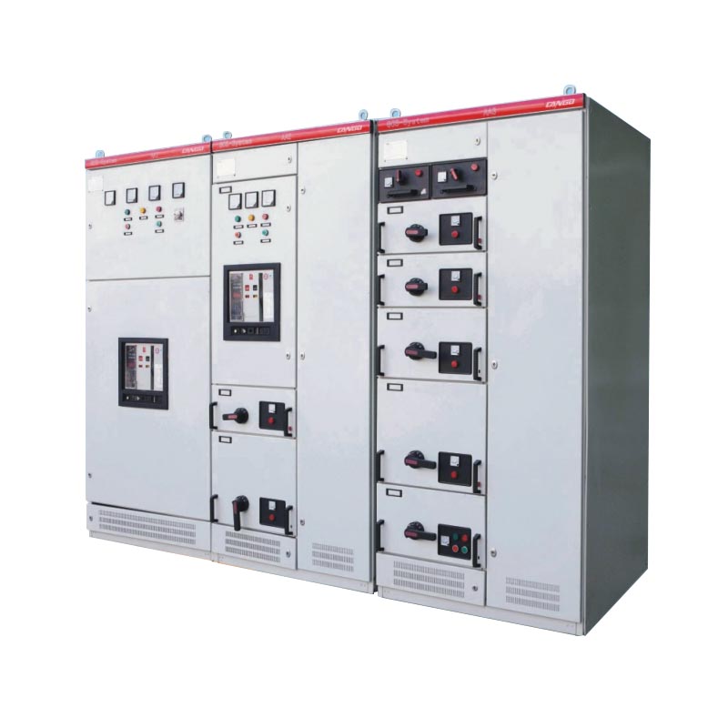
GCS Low-Voltage Withdrawable Switchgear
Model GCS
Low-voltage withdrawable switchgear for distribution and motor-control applications. Functional units, busbar configuration, auxiliary circuits and short-circuit ratings are selected to match the project requirements.
Share your rated data, quantity and project requirements.
View this model in our 2026 catalog ↗
Project configuration reviewTechnical documentation support
Product Overview
GCS low-voltage withdrawable switchgear is used for power distribution, motor centralized control, and reactive power compensation. It is commonly used for industrial power distribution and motor centralized control, with the final selection based on rated data, drawings, and site conditions.
panel builders, EPC companies, electrical contractors, industrial users, and overseas distributors can request configuration review for withdrawable low-voltage switchgear for motor centralized control and reactive compensation. Please send main circuit scheme, busbar current, feeder arrangement, drawer or fixed cabinet structure, protection, and installation layout, quantity, destination, and any project standard requirements for quotation.
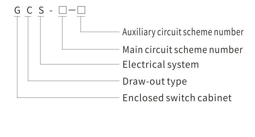
Model and Meaning
- GCS: enclosed draw-out switchgear system
- Confirm the main-circuit scheme number and auxiliary-circuit scheme number
Technical Specifications
GCS Technical Parameter Table
Review the GCS rated data, selected configuration, and project requirements before quotation.
| Group | Item | Unit | Parameter |
|---|---|---|---|
| Main circuit rated voltage | V | AC 380 (400) / 660 | |
| Auxiliary circuit rated voltage | V | AC 220 / 380 (400); DC 110 / 220 | |
| Rated frequency | Hz | 50 (60) | |
| Rated insulation voltage | V | 660 (1000) | |
| Rated current | Horizontal busbar | A | <= 4000 |
| Vertical busbar (MCC) | A | 1000 | |
| Busbar rated short-time withstand current | kA / 1 s | 50 / 80 | |
| Busbar rated peak withstand current | kA / 0.1 s | 105 / 176 | |
| Power-frequency test voltage | Main circuit | V / 1 min | 2500 |
| Auxiliary circuit | V / 1 min | 1760 | |
| Busbar | Three-phase four-wire system | A.B.C.PEN | |
| Three-phase five-wire system | A.B.C.PE.N | ||
| Protection level | IP30 / IP40 |
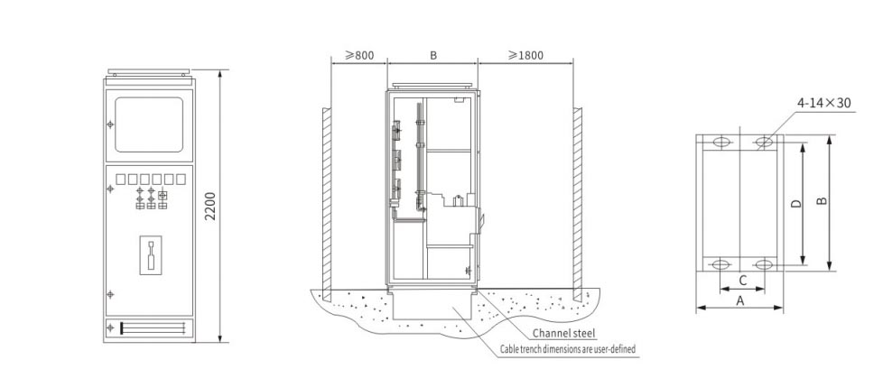
Installation Dimensions / Drawing
Applications
GCS is mainly selected for industrial power distribution and motor centralized control. The final application should match the confirmed withdrawable low-voltage switchgear for motor centralized control and reactive compensation, rated data, and site installation conditions.
- Industrial power distribution
- Motor centralized control
- Reactive power compensation projects
Ordering Instructions / Information Required for Quotation
ForGCS, send main circuit scheme, busbar current, feeder arrangement, drawer or fixed cabinet structure, protection, and installation layout, quantity, destination, and the expected delivery schedule. The engineering review will be based on the selected withdrawable low-voltage switchgear for motor centralized control and reactive compensation and project drawing.
ORDERING INSTRUCTIONS
- Provide the full product model, including the main-circuit and auxiliary-circuit scheme numbers.
- Provide the main-circuit system combination sequence diagram and auxiliary-circuit electrical schematic.
- Provide the cabinet component list, circuit-setting parameters, and any special requirements outside normal use conditions.
EXPLORE THE RANGE
Related equipment