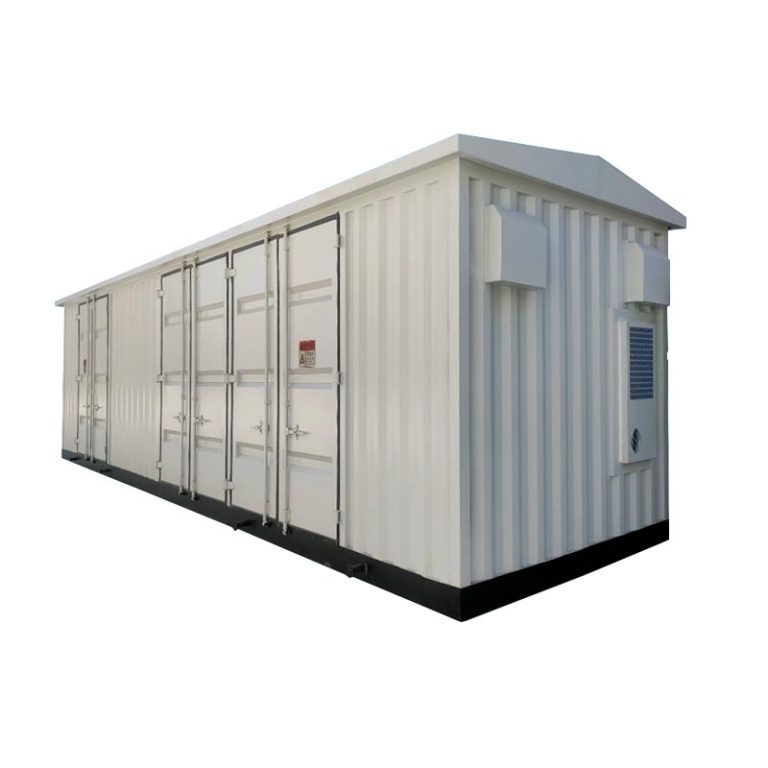
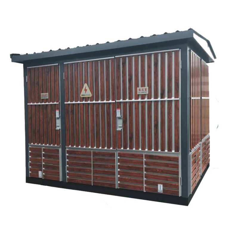
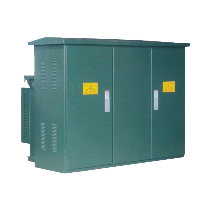
Prefabricated Substations
ZGS11-12 Box Type Transformer Substation
Model ZGS11-12
An American-style combined prefabricated substation for 10 kV ring-network, dual-source or terminal supply systems. Brings transformation, metering, compensation, control and protection functions into a compact project configuration.
Share your rated data, quantity and project requirements.
View this model in our 2026 catalog ↗
Project configuration reviewTechnical documentation support
Product Overview
ZGS11-12 combined American prefabricated substation is intended for 10 kV ring network, dual power supply, or terminal power supply systems. It is commonly used for residential areas, parks, stations, and hotels and construction sites, airports, and related distribution projects, with the final selection based on rated data, drawings, and site conditions.
EPC companies, electrical contractors, utilities, developers, and overseas distributors can request configuration review for american prefabricated substation. Please send transformer capacity, HV/LV voltage combination, enclosure layout, foundation drawing, and incoming / outgoing cable scheme, quantity, destination, and any project standard requirements for quotation.
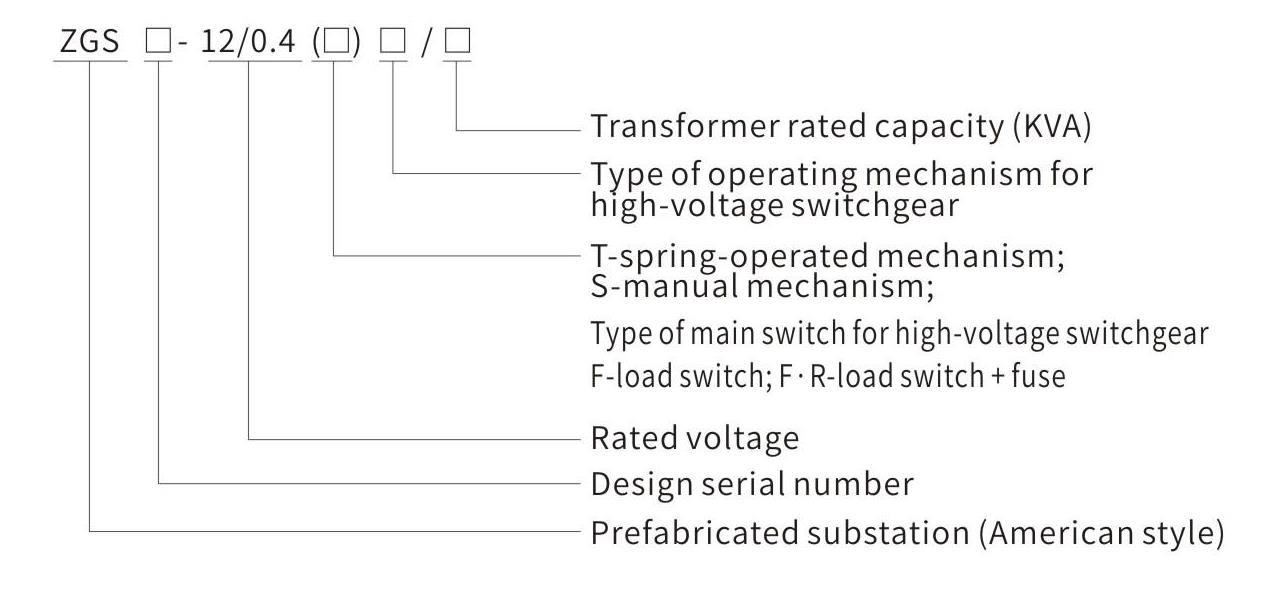
Model and Meaning
- ZGS: American-style prefabricated substation
- 12: rated-voltage class
- Select the transformer rated capacity, high-voltage switchgear main-switch type, and operating-mechanism type for the ordered configuration
Technical Specifications
Transformer performance parameters for 10kV combined transformer S9, S10, and S11 oil-immersed series
Review the ZGS11-12 capacity, voltage combination, loss data, impedance, and selected configuration before quotation.
| Serial | Rated capacity | Rated voltage | Voltage adjustment range | Connection | No-load current (%) | No-load loss (W) | Load loss (W) | Reference | ||||||
|---|---|---|---|---|---|---|---|---|---|---|---|---|---|---|
| Serial number | kVA | High voltage (kV) | Low voltage (kV) | % | Group number | S9 | S10 / S11 | S9 | S10 | S11 | S9 / S10 / S11 | Impedance voltage (%) | Noise (dB) | Temperature rise (K) |
| 1 | 30 | 6 | 0.4 | +/-5 | Yyn0 | 2.2 | 2.0 | 130 | 110 | 100 | 600 | 4 | 55 | Top oil 55; coil 65 |
| 2 | 50 | 6 | 0.4 | +/-5 | Yyn0 | 2.0 | 1.8 | 170 | 150 | 130 | 870 | 4 | 55 | Top oil 55; coil 65 |
| 3 | 63 | 6 | 0.4 | +/-5 | Yyn0 | 1.9 | 1.5 | 200 | 180 | 150 | 1049 | 4 | 55 | Top oil 55; coil 65 |
| 4 | 80 | 6 | 0.4 | +/-5 | Yyn0 | 1.7 | 1.2 | 250 | 200 | 180 | 1250 | 4 | 55 | Top oil 55; coil 65 |
| 5 | 100 | 6 | 0.4 | +/-5 | Yyn0 | 1.6 | 1.1 | 290 | 230 | 200 | 1500 | 4 | 55 | Top oil 55; coil 65 |
| 6 | 125 | 6 | 0.4 | +/-5 | Yyn0 | 1.5 | 1.0 | 340 | 270 | 240 | 1800 | 4 | 55 | Top oil 55; coil 65 |
| 7 | 160 | 6 | 0.4 | +/-5 | Yyn0 | 1.4 | 1.0 | 400 | 310 | 280 | 2200 | 4 | 55 | Top oil 55; coil 65 |
| 8 | 200 | 6 | 0.4 | +/-5 | Yyn0 | 1.4 | 0.8 | 480 | 380 | 340 | 2600 | 4 | 55 | Top oil 55; coil 65 |
| 9 | 250 | 6.3 | 0.4 | +/-5 | Yyn0 | 1.2 | 0.8 | 560 | 460 | 400 | 3050 | 4 | 55 | Top oil 55; coil 65 |
| 10 | 315 | 6.3 | 0.4 | +/-5 | Yyn0 | 1.1 | 0.7 | 670 | 540 | 480 | 3650 | 4 | 55 | Top oil 55; coil 65 |
| 11 | 400 | 6.3 | 0.4 | +/-5 | Yyn0 | 1.0 | 0.7 | 800 | 650 | 570 | 4300 | 4 | 55 | Top oil 55; coil 65 |
| 12 | 500 | 10 | 0.69 | +/-2 x 2.5 | Dyn11 | 1.0 | 0.6 | 960 | 780 | 680 | 5150 | 4 | 55 | Top oil 55; coil 65 |
| 13 | 630 | 10 | 0.69 | +/-2 x 2.5 | Dyn11 | 0.9 | 0.6 | 1200 | 920 | 810 | 6200 | 4.5 | 55 | Top oil 55; coil 65 |
| 14 | 800 | 10 | 0.69 | +/-2 x 2.5 | Dyn11 | 0.8 | 0.6 | 1400 | 1120 | 980 | 7500 | 4.5 | 55 | Top oil 55; coil 65 |
| 15 | 1000 | 10 | 0.69 | +/-2 x 2.5 | Dyn11 | 0.7 | 0.5 | 1700 | 1320 | 1150 | 10300 | 4.5 | 55 | Top oil 55; coil 65 |
| 16 | 1250 | 10 | 0.69 | +/-2 x 2.5 | Dyn11 | 0.6 | 0.5 | 1950 | 1560 | 1360 | 12000 | 4.5 | 55 | Top oil 55; coil 65 |
| 17 | 1600 | 10 | 0.69 | +/-2 x 2.5 | Dyn11 | 0.6 | 0.5 | 2400 | 1880 | 1640 | 14500 | 4.5 | 55 | Top oil 55; coil 65 |
Note: the high-voltage tapping range can be designed as +/-2 x 2.5% according to user requirements; the low-voltage side can be designed as 0.69kV according to user requirements.
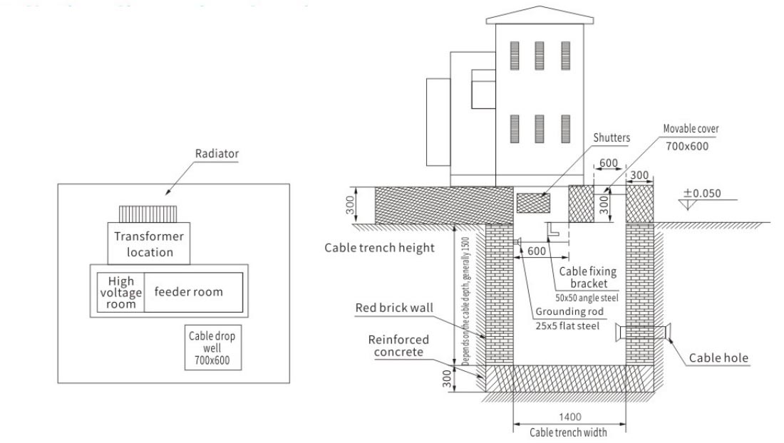
Installation Dimensions / Drawing
Applications
ZGS11-12 is mainly selected for residential areas, parks, stations, and hotels and construction sites, airports, and related distribution projects. The final application should match the confirmed american prefabricated substation, rated data, and site installation conditions.
- Residential areas, parks, stations, and hotels
- Construction sites, airports, and related distribution projects
- 10 kV ring network or terminal power supply systems
Ordering Instructions / Information Required for Quotation
ForZGS11-12, send transformer capacity, HV/LV voltage combination, enclosure layout, foundation drawing, and incoming / outgoing cable scheme, quantity, destination, and the expected delivery schedule. The engineering review will be based on the selected american prefabricated substation and project drawing.
ORDERING INSTRUCTIONS
- Provide the operating site and any special requirements.
- Provide ordering drawings with wiring diagrams, transformer capacity, main-component models, specifications, branch circuits, and capacity.
- State metering and reactive-power compensation requirements when applicable.
- State surface-treatment requirements and whether the combined transformer is terminal type or ring-network type.
EXPLORE THE RANGE
Related equipment